Carbon fiber composite foam core sandwich structure wind tunnel fan blade and molding method

A technology of sandwich structures and composite materials, applied in liquid fuel engines, components of pumping devices for elastic fluids, non-variable displacement pumps, etc.

Active Publication Date: 2015-02-18
AEROSPACE RES INST OF MATERIAL & PROCESSING TECH +1
View PDF6 Cites 24 Cited by
  • Summary
  • Abstract
  • Description
  • Claims
  • Application Information

AI Technical Summary

Problems solved by technology

[0004] The purpose of the present invention is to solve the problem of manufacturing high-performance wind tunnel fan blades, and propose a high-performance carbon fiber composite material foam sandwich structure wind tunnel fan blade and its forming method

Method used


Image

  • Carbon fiber composite foam core sandwich structure wind tunnel fan blade and molding method
  • Carbon fiber composite foam core sandwich structure wind tunnel fan blade and molding method
  • Carbon fiber composite foam core sandwich structure wind tunnel fan blade and molding method

Examples


Embodiment 1

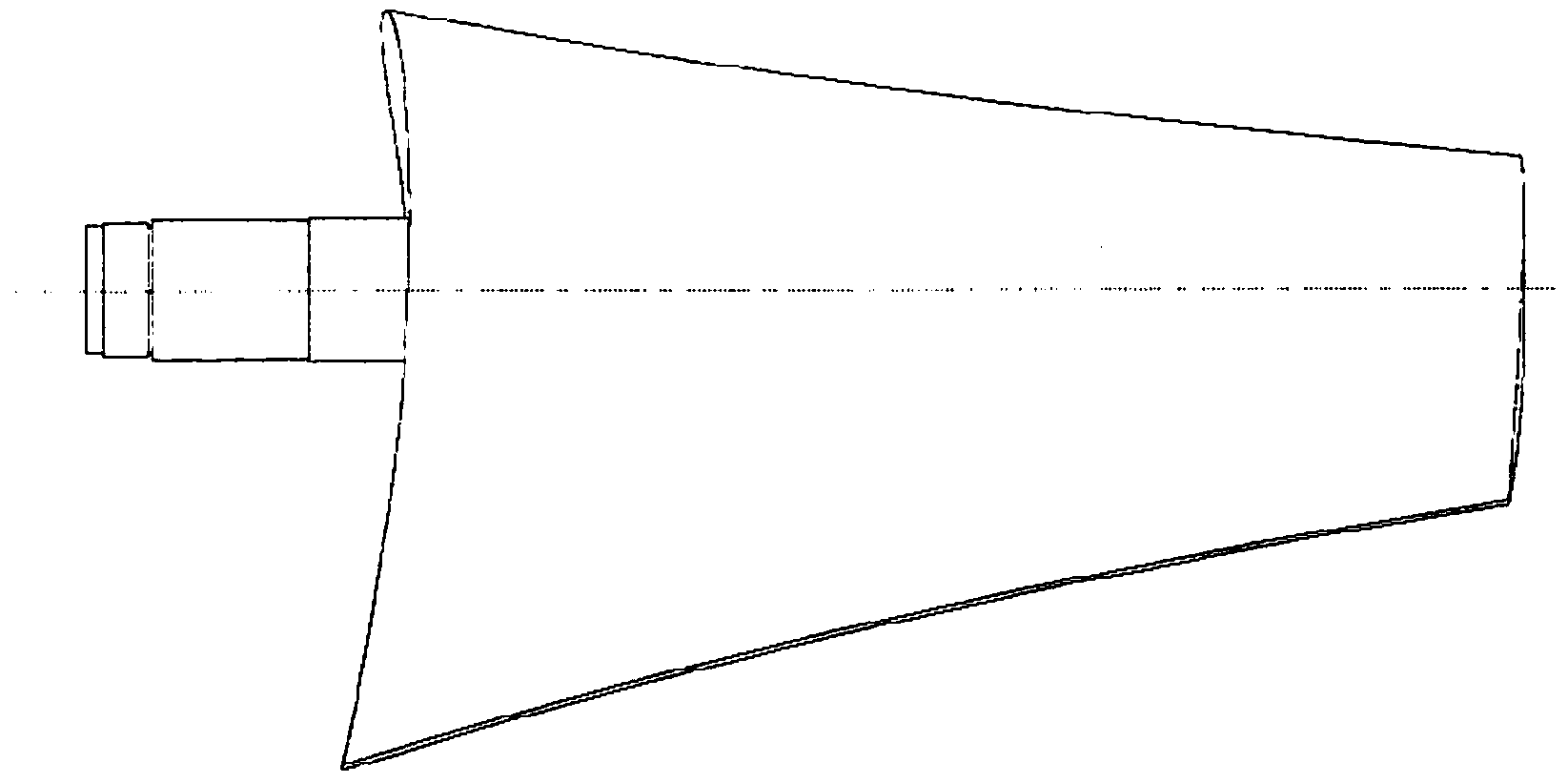
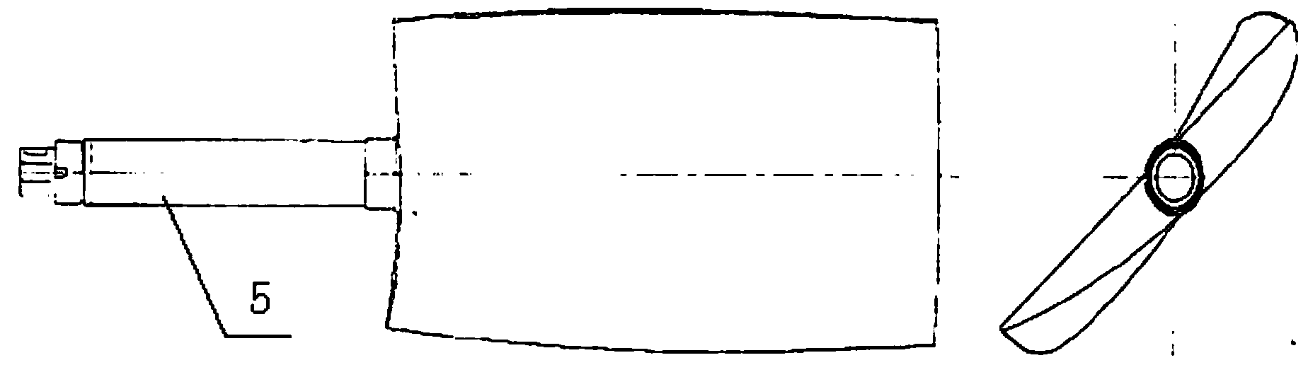
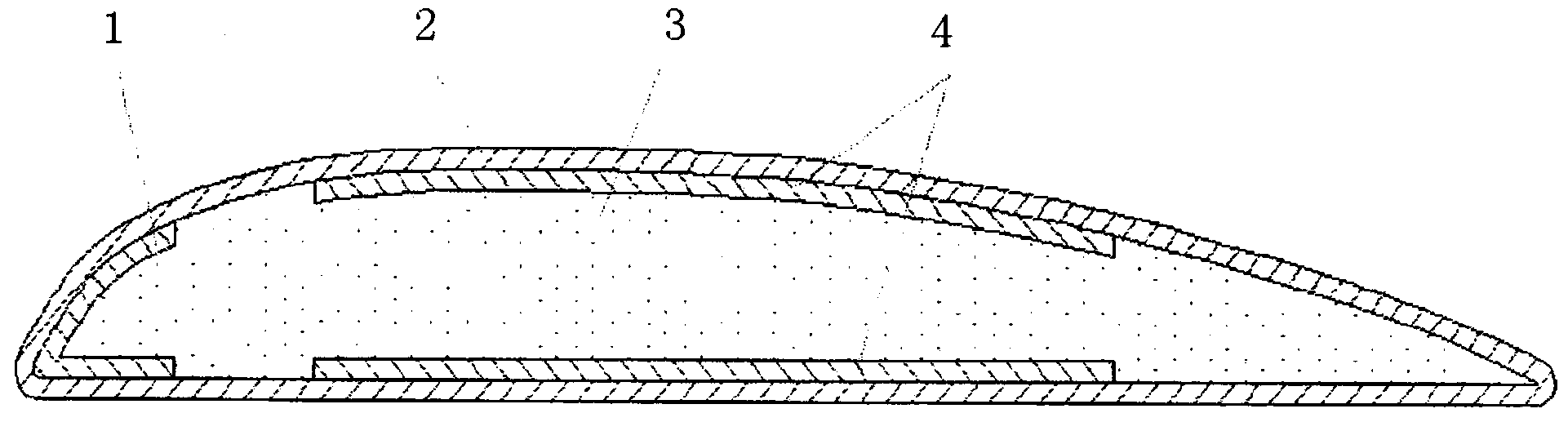
[0032] Such as Figure 1 to Figure 3 As shown, a carbon fiber composite material foam sandwich structure wind tunnel fan blade according to the present invention, the blade is an integral foam sandwich structure, the blade root is connected to a metal petiole 5; the blade includes a skin 2, a leading edge reinforcement area 1 , the main load-bearing beam 4 and the foam core material 3, wherein the outer part is the skin 2, the inner front end of the skin 2 is connected to the front edge reinforcement area 1, the inner middle of the skin 2 is connected to the main load-bearing beam 4, and the foam core material 3 is filled in the cover The inner space formed by the skin 2, the front edge reinforcement area 1 and the main bearing beam 4; the skin 2 is divided into an inner skin and an outer skin, and the inner skin is covered with an outer skin;

[0033] The thickness of the main bearing beam 4 transitions from 9.75mm at the blade root to 3.75mm at the blade tip, and the gradual...

Embodiment 2

[0053] Such as Figure 1 to Figure 3 As shown, a carbon fiber composite material foam sandwich structure wind tunnel fan blade according to the present invention, the blade is an integral foam sandwich structure, the blade root is connected to a metal petiole 5; the blade includes a skin 2, a leading edge reinforcement area 1 , the main load-bearing beam 4 and the foam core material 3, wherein the outer part is the skin 2, the inner front end of the skin 2 is connected to the front edge reinforcement area 1, the inner middle of the skin 2 is connected to the main load-bearing beam 4, and the foam core material 3 is filled in the cover The inner space formed by the skin 2, the front edge reinforcement area 1 and the main bearing beam 4; the skin 2 is divided into an inner skin and an outer skin, and the inner skin is covered with an outer skin;

[0054] The thickness of the main bearing beam 4 transitions from 8 mm at the root of the blade to 2 mm at the tip of the blade, and t...

Embodiment 3

[0074] Such as Figure 1 to Figure 3 As shown, a carbon fiber composite material foam sandwich structure wind tunnel fan blade according to the present invention, the blade is an integral foam sandwich structure, the blade root is connected to a metal petiole 5; the blade includes a skin 2, a leading edge reinforcement area 1 , the main load-bearing beam 4 and the foam core material 3, wherein the outer part is the skin 2, the inner front end of the skin 2 is connected to the front edge reinforcement area 1, the inner middle of the skin 2 is connected to the main load-bearing beam 4, and the foam core material 3 is filled in the cover The inner space formed by the skin 2, the front edge reinforcement area 1 and the main bearing beam 4; the skin 2 is divided into an inner skin and an outer skin, and the inner skin is covered with an outer skin;

[0075] The thickness of the main bearing beam 4 transitions from 10 mm at the root of the blade to 4 mm at the tip of the blade, and ...


PUM

PropertyMeasurementUnit
thicknessaaaaaaaaaa
thicknessaaaaaaaaaa
thicknessaaaaaaaaaa

Abstract

The invention provides a carbon fiber composite foam core sandwich structure wind tunnel fan blade. The wind tunnel fan blade is characterized in that a skin is arranged at the outer part; the internal front end of the skin is connected to a front edge reinforcing area; the internal middle part of the skin is connected with a main bearing beam; an internal space defined by the skin, the front edge reinforcing area and the main bearing beam is filled with a foam core material; the skin comprises an inner skin and an outer skin; the outer skin is laid and adhered to the surface of the inner skin; the thickness of the main bearing beam is changed from 8-10 mm at the root part of the blade to 2-4 mm at the tip of the blade; the thickness of the front edge reinforcing area is 2-5 mm, the thickness of the inner skin is 2-5 mm, and the thickness of the outer skin is 1-3 mm. A molding method comprises the following steps: (a), pasting a blade handle with the foam core material; (b), feeding prepreg; (c), performing paving and glue suction compaction on the front edge reinforcing area and the main bearing beam; (d), performing paving and glue suction compaction on the inner skin; (e), solidifying; (f), molding the outer skin. According to the invention, the high-performance wind tunnel fan blade can be produced, and the use requirements under low-temperature, high-pressure, high-humidity and normal-temperature vacuum simulated climate environments can be met.

Description

technical field [0001] The invention belongs to the technical field of advanced composite materials, and relates to a high-performance carbon fiber composite material wind tunnel fan blade and a forming method thereof. Background technique [0002] Most of the existing wind tunnel fan blades are made of metal or fiberglass, which can meet the requirements of use under low speed and low environmental conditions (the speed is not more than 300 rpm, without harsh low temperature conditions). However, high-performance wind tunnel fan blade materials need to meet the requirements of light weight, small thermal deformation, and high mechanical properties under conventional conditions and special working conditions, so general metal and FRP blades are difficult to meet. [0003] Carbon fiber reinforced composite materials have the characteristics of light weight, small thermal deformation, high strength and rigidity under different use environments, and are suitable for manufacturi...

Claims


Application Information

Patent Timeline
Patent Type & Authority Applications(China)
IPC IPC(8): F04D29/26B29C70/40
CPCB29C70/40F04D29/023F04D29/26
Inventor 杨智勇刘千蔡勇孙宝岗尹亮张毅黄凤春冷霜罗业游少雄
Owner AEROSPACE RES INST OF MATERIAL & PROCESSING TECH
Why Eureka
Try Eureka