Steel box girder mounting method

An installation method and technology of steel box girder, applied in bridges, bridge materials, bridge construction and other directions, can solve the problems of unfavorable and smooth closing of steel box girder inclination, unable to meet the actual use, etc., to achieve convenient closing, good use effect, and guarantee stability. effect of marching

Pending Publication Date: 2021-01-22
金徽
View PDF1 Cites 0 Cited by
  • Summary
  • Abstract
  • Description
  • Claims
  • Application Information

AI Technical Summary

Problems solved by technology

[0004] In summary, the prior art proposed above cannot solve the situation that the inclination of the steel box girder is not conducive to the smooth closing during the installation process, so it cannot meet the needs of actual use

Method used


Image

  • Steel box girder mounting method
  • Steel box girder mounting method
  • Steel box girder mounting method

Examples


Embodiment 1

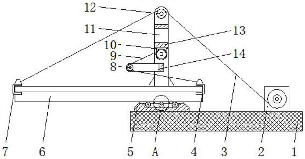
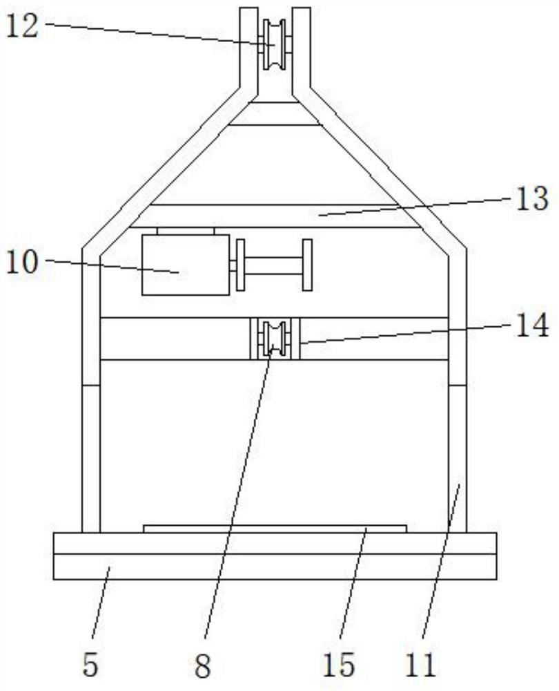
[0027] A steel box girder installation structure, comprising a bridge body 1, a base 5 and a bracket 11, the upper surface of the bridge body 1 is equipped with a base 5, the upper surface of the base 5 is welded with a bracket 11, and one side of the base 5 is provided with a second A hoist 2, a second hoist 10 is installed inside the bracket 11, the first hoist 2 is fixed on the completed section of the bridge body 1, and the first hoist 2 and the surface of the bridge body 1 are reinforced by bolts to avoid loosening. The base 5 is also a completed section fixed on the bridge body 1, reinforced by bolts, and can be disassembled and installed flexibly for continuous use.

[0028] The inner wall of the lower end of the support 11 is welded with an extension frame 14, and the extension frame 14 is equipped with a first pulley 8 inside the end away from the support 11, and the second hoist 10 is located at the upper end of the extension frame 14. The steel cable 9 is sleeved on...

Embodiment 2

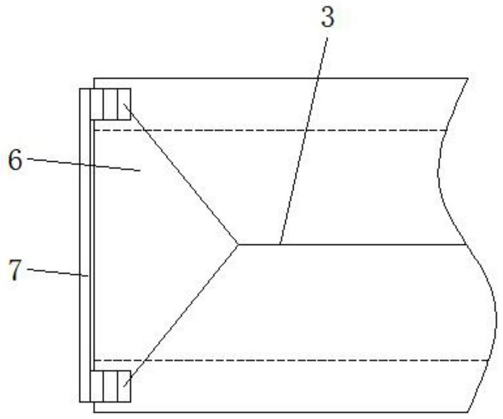
[0033] A method for installing a steel box girder, comprising a first hoist 2 and a second hoist 10, characterized in that the first hoist 2 pulls the second ferrule 7 through the first steel cable 3 to move, and the second hoist 10 moves through the second steel The cable 9 pulls the first ferrule 4 to move.

[0034]The first hoist 2 can tighten and release the first steel cable 3 slowly. When one end of the steel box girder body 6 is sleeved on the second ferrule 7, the first steel cable 3 connected to the second ferrule 7 is subjected to the first The traction of the winch 2, when the steel box girder body 6 is advancing, the first steel cable 3 can lift the front end of the steel box girder body 6, and the forward end of the steel box girder body 6 remains horizontal to facilitate docking, and the second pulley 12 can increase the hoisting moment of the first wire rope 3.

[0035] When the second hoist 10 is rewinding the second steel cable 9, the second steel cable 9 wil...


PUM


Abstract

The invention discloses a steel box girder mounting method which comprises the steps that a first winch drags a second clamping sleeve to move through a first steel cable, a second winch drags the first clamping sleeve to move through a second steel cable, and when the second winch winds the second steel cable, the second steel cable can pull the first clamping sleeve to move; the second steel cable pulls the first clamping sleeve to move horizontally, the steel box girder body can be pushed, the second steel cable drives the first clamping sleeve to push the steel box girder body, in the pushing process of the steel box girder body, the first steel cable can be stretched, the first winch can tighten the first steel cable, and the first winch can slowly release the first steel cable, so that the steel box girder body is kept horizontal in the propelling process, and closure of the steel box girder body is more convenient. Through cooperative use of the first winch and the second winch,stable advancing of the steel box girder body in the mounting process is guaranteed.

Description

technical field [0001] The invention relates to the technical field of bridge erection, in particular to a steel box girder installation method. Background technique [0002] Steel box girder, also known as steel plate box girder, is a commonly used structural form of long-span bridges. Generally used on bridges with large spans, it is called steel box girder because it looks like a box. When erecting steel box girders, large-scale lifting equipment is usually used for hoisting, and then placed in the pre-installation position for installation of steel box girders. However, when large-scale lifting equipment is used for operation, large-scale lifting equipment will occupy a lot of ground space. Moreover, most bridges are erected above the road surface. When using large-scale lifting equipment, the road surface will be occupied and traffic jams will be caused. At the same time, when the push-type erection method is carried out, the traditional erection method cannot effecti...

Claims


Application Information

Patent Timeline
IPC IPC(8): E01D21/00E01D2/04E01D101/30
CPCE01D2/04E01D21/00E01D2101/30
Inventor 金徽郭海玲
Owner 金徽
Why Eureka
Try Eureka