
Hydraulic part testing tool

A technology for testing tooling and hydraulic parts, applied in the field of hydraulic parts, can solve problems such as troublesome operation and waste of time, and achieve the effect of convenient output

Inactive Publication Date: 2021-01-29
CHANGDE HUAHAI HYDRAULIC MACHINERY MFG
View PDF0 Cites 0 Cited by
  • Summary
  • Abstract
  • Description
  • Claims
  • Application Information

AI Technical Summary

Problems solved by technology

[0003] The piston rod of the hydraulic cylinder needs to bear pressure as the power output end. In order to ensure the quality of the piston rod of the hydraulic cylinder, a test is performed before leaving the factory to test the pressure of the piston rod. However, the pressure test of the piston rod is generally done manually by workers. Putting the piston rod into the machine for testing, taking it out, and putting it back in again, this operation is cumbersome and time-consuming, thus a hydraulic component testing tool is proposed

Method used


Image

  • Hydraulic part testing tool
  • Hydraulic part testing tool
  • Hydraulic part testing tool

Examples


Embodiment Construction

[0020] In order to make the object, technical solution and advantages of the present invention clearer, the present invention will be further described in detail below in combination with specific embodiments and with reference to the accompanying drawings. It should be understood that these descriptions are exemplary only, and are not intended to limit the scope of the present invention. Also, in the following description, descriptions of well-known structures and techniques are omitted to avoid unnecessarily obscuring the concept of the present invention.

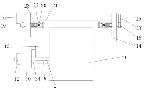
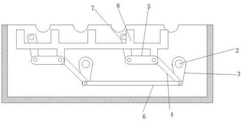
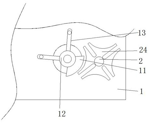
[0021] Such as Figure 1-3 As shown, a hydraulic component testing tool proposed by the present invention includes a conveying shell 1, the inner side of the conveying shell 1 is rotationally connected with symmetrically distributed first rotating shafts 2, and the outer sides of the two first rotating shafts 2 are fixedly connected with rotating blocks 3 , the bottoms of the two rotating blocks 3 are hinged with one end...


PUM


Abstract

The invention discloses a hydraulic part testing tool. The hydraulic part testing tool comprises a conveying shell, wherein the inner side of the conveying shell is rotatably connected to first rotating shafts which are symmetrically distributed, the outer sides of the two first rotating shafts are both fixedly connected to rotating blocks, the bottoms of the two rotating blocks are both hinged toone ends of first connecting rods, one ends of second connecting rods are hinged to the other ends of the two first connecting rods, swing rods are hinged to the other ends of the two second connecting rods, and one ends of third connecting rods are hinged to the bottoms of the two rotating blocks. According to the tool, through cooperation of the first rotating shafts, the rotating blocks, a conveying frame, the second connecting rods and the like, the conveying frame moves periodically, piston rods are conveyed on an arc-shaped groove piece by piece in sequence, and through cooperation of atransmission rod, a limiting plate, a rotating plate and the like, the conveying frame can move intermittently, and the piston rods can be tested conveniently when the conveying frame stops.

Description

technical field [0001] The invention relates to the technical field of hydraulic parts, in particular to a testing tool for hydraulic parts. Background technique [0002] Hydraulic parts are hydraulic pumps, hydraulic motors, hydraulic cylinders, hydraulic valves, boosters and other components used in hydraulic systems. Hydraulic cylinders are important machinery and are used in various industries. [0003] The piston rod of the hydraulic cylinder needs to bear pressure as the power output end. In order to ensure the quality of the piston rod of the hydraulic cylinder, a test is performed before leaving the factory to test the pressure of the piston rod. However, the pressure test of the piston rod is generally done manually by workers. Putting the piston rod into the machine for testing, then taking it out and putting it back in again, this operation is cumbersome and time-consuming, thus a hydraulic component testing tool is proposed. Contents of the invention [0004] ...

Claims


Application Information

Patent Timeline
IPC IPC(8): F15B19/00F15B15/14
CPCF15B15/1457F15B19/005
Inventor 周东洋
Owner CHANGDE HUAHAI HYDRAULIC MACHINERY MFG
Learn More