Valve diaphragm with high fatigue performance

A fatigue performance and valve technology, which is applied in the field of valve diaphragms with high fatigue performance, can solve problems such as poor sealing performance and fatigue life that cannot meet the technical index requirements, and achieve the effect of improving sealing and fatigue life

Inactive Publication Date: 2021-01-29
AVIC BEIJING INST OF AERONAUTICAL MATERIALS
View PDF6 Cites 0 Cited by
  • Summary
  • Abstract
  • Description
  • Claims
  • Application Information

AI Technical Summary

Problems solved by technology

[0002] For the valve diaphragm structure with reciprocating motion, the existing valve diaphragm often adopts an equal-thickness design to reduce the difficulty of the molding process, or designs a boss at the sealing position of the bellows to improve the local sealing performance. This type of diaphragm is not poor in sealing performance. Good, but the fatigue life does not meet the requirements of technical indicators

Method used


Image

  • Valve diaphragm with high fatigue performance
  • Valve diaphragm with high fatigue performance

Examples


Embodiment 1

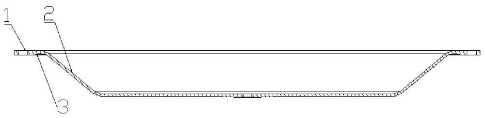
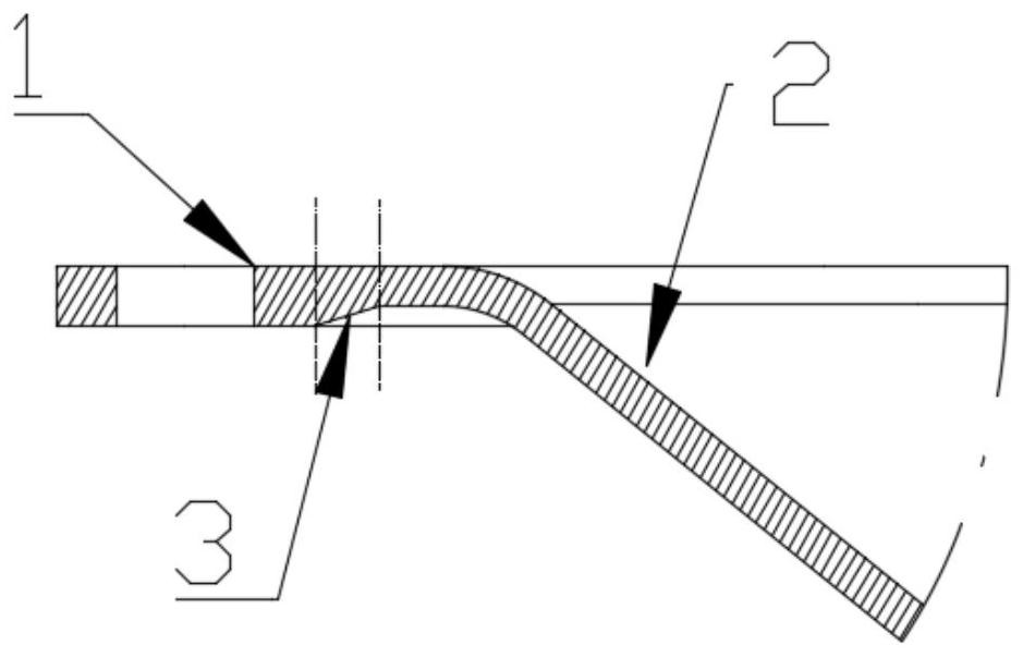
[0033] Select the included angle between the inclined plane and the central plane of the reciprocating flexing area (2) to be 135°; select the transition fillet radius between the central plane and the inclined plane of the reciprocating flexing area (2) to be 16 mm, and the inclined plane and the connecting surface The transition fillet radius between them is 16mm.

[0034] The thickness of the installation sealing area (1) is selected as 6mm, and the thickness of the reciprocating flexing area (2) is respectively selected as 4, 5, and 6mm, so the fatigue life ratio of the valve diaphragm is 28:23:19.

Embodiment 2

[0036] The thickness of the installation sealing area (1) is selected to be 6mm, and the thickness of the reciprocating flexing area (2) is respectively selected to be 4mm; The transition fillet radius between the connecting faces is 16mm.

[0037] The included angles between the inclined plane and the central plane of the reciprocating flexing area (2) are 135°, 138°, 140°, and 143° respectively, and the fatigue life ratio of the valve diaphragm is 27.5:22:14:12.

Embodiment 3

[0039] The included angle between the slope of the reciprocating flexing area (2) and the central plane is 135°; the thickness of the installation sealing area (1) is selected to be 6 mm, and the thickness of the reciprocating flexing area (2) is respectively selected to be 4 mm.

[0040] The transition fillet radius between the central plane and the inclined plane of the reciprocating flexing area (2) is the same as the transition fillet radius between the inclined plane and the connecting surface, respectively select 9:11:14:16mm, then the fatigue of the valve diaphragm The life ratio is 26:27:28:30.


PUM


Abstract

The invention discloses a valve diaphragm with high fatigue performance, and belongs to the technical field of regulating valves. The edge of the valve diaphragm is provided with an installation sealing area (1) fixedly connected with the periphery of an upper diaphragm capsule and the periphery of a lower diaphragm capsule, and the center of the valve diaphragm is a reciprocating flexing area (2)capable of moving in a reciprocating mode after being stressed; the thickness of the installation sealing area (1) is larger than that of the reciprocating flexing area (2), and a transition step (3)is formed between the installation sealing area (1) and the reciprocating flexing area (2) of the valve diaphragm; the installation sealing area (1) of the valve diaphragm is fixed to the periphery of the upper diaphragm capsule and the periphery of the lower diaphragm capsule, and the space between the upper diaphragm capsule and the lower diaphragm capsule is sealed; the inner side of the transition step (3) does not make contact with the upper diaphragm capsule and the lower diaphragm capsule when the valve diaphragm is not in the working state; and when the valve diaphragm works, the reciprocating flexing area (2) does reciprocating movement under the action of valve air pressure. The valve diaphragm is provided with the step, so that the fatigue performance of the valve diaphragm canbe remarkably improved.

Description

technical field [0001] The invention relates to a valve diaphragm with high fatigue performance and belongs to the technical field of regulating valves. Background technique [0002] For the valve diaphragm structure with reciprocating motion, the existing valve diaphragm often adopts an equal-thickness design to reduce the difficulty of the molding process, or designs a boss at the sealing position of the bellows to improve the local sealing performance. This type of diaphragm is not poor in sealing performance. Good, that is, the fatigue life does not meet the technical index requirements. According to calculations, increasing the valve diaphragm thickness can increase its sealing performance, and reducing the valve diaphragm thickness can increase its fatigue performance, which has caused a design contradiction for the valve diaphragm thickness. In order to solve such contradictions, the present invention designs a A structure with thicker edges and thinner middle enhanc...

Claims


Application Information

Patent Timeline
Patent Type & Authority Applications(China)
IPC IPC(8): F16K7/12F16K31/126
CPCF16K7/12F16K31/126
Inventor 徐时贤蒋洪罡焦冬生任宗文苏正涛李红波
Owner AVIC BEIJING INST OF AERONAUTICAL MATERIALS
Why Eureka
Try Eureka