Target mode position measurement method and system, storage medium and equipment

A measurement method and target technology, applied in character and pattern recognition, image analysis, image enhancement, etc., can solve problems affecting positioning accuracy, hidden safety hazards, blurred boundaries of target objects, etc., and achieve rapid 3D modeling and wide application space Effect

Pending Publication Date: 2021-01-29
山东产研信息与人工智能融合研究院有限公司
View PDF6 Cites 2 Cited by
  • Summary
  • Abstract
  • Description
  • Claims
  • Application Information

AI Technical Summary

Problems solved by technology

[0004] Generally, multiple continuous images are required to realize the spatial positioning of the target object; when the target object is large or has a certain volume / area, but only one point coordinates, for many scenes, such as traffic control and robot inspection, it will cause serious problems The fuzzy boundary of the target object affects the positioning accuracy and has certain security risks

Method used


Image

  • Target mode position measurement method and system, storage medium and equipment
  • Target mode position measurement method and system, storage medium and equipment
  • Target mode position measurement method and system, storage medium and equipment

Examples


Embodiment 1

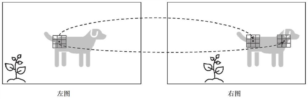
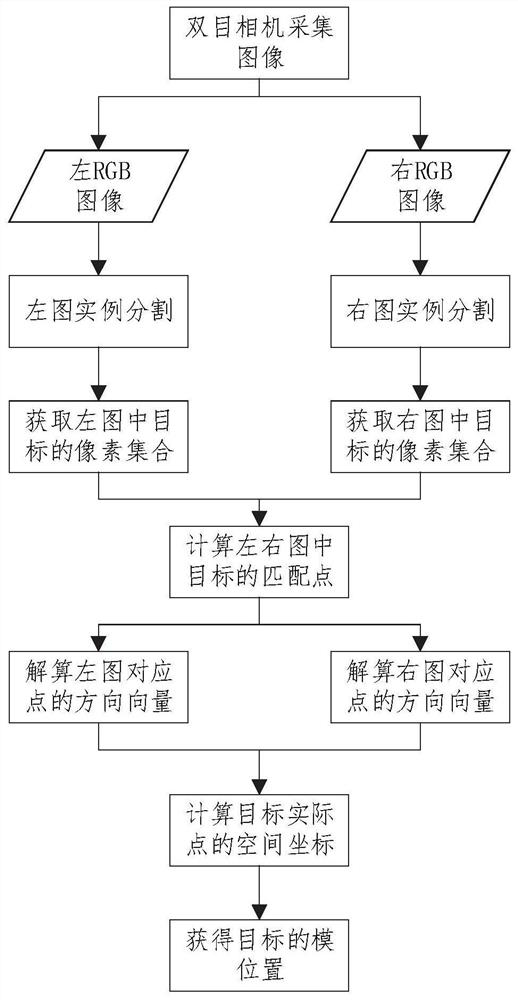
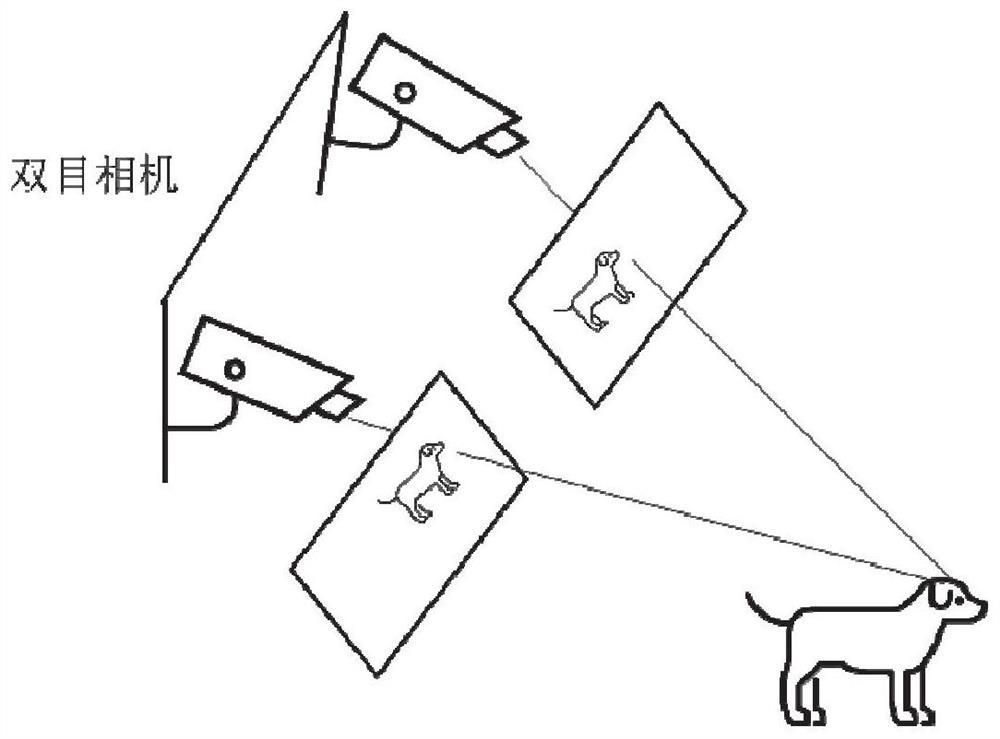
[0048] This embodiment proposes a method for measuring the position of a target module based on a binocular camera. Such as figure 1 As shown in Fig. 1, the left and right images of the target entity are first collected by a binocular camera. Instance segmentation is performed on the left and right images respectively to obtain the target entity to be measured in the image, and the pixel set of the target to be measured in the left and right images is obtained. Taking the left image as the reference image, the pixel points of the target in the two images are matched to obtain the one-to-one correspondence between the target pixel points in the left and right images.

[0049] Solve the poses of the two cameras using the pixel and world coordinates of the known reference fiducials. Based on the camera pose and the pixel coordinates of the target to be measured, the spatial direction vector of the target point is calculated. After obtaining the spatial direction vectors of the...

Embodiment 2

[0073] Utilize the method of embodiment 1 to the positioning of the packing box (such as a cube box) in the industrial automation production workshop: by measuring the mold position of the cube box in an industrial automation production scene, the position and occupied space of the cube box in the scene can be obtained, and the manipulator According to the mold position of the box, it can be accurately grasped.

Embodiment 3

[0075] The method of Embodiment 1 is used to locate each electric device in the substation, determine the boundary of the electric device, and mark the above-mentioned boundary in the patrol inspection task, so as to control the robot to avoid obstacles.

[0076] In addition, the following product examples are provided:


PUM


Abstract

The invention provides a target mode position measurement method and system, a storage medium and equipment. The method comprises the following steps: acquiring two images of a target object at different positions; segmenting the two images to obtain a target object to be measured in the images, and obtaining a pixel set of the target object; taking one of the images as a reference image, and matching pixel points of the target object in the two images to obtain a corresponding relation of the pixel points of the target object in the two images; solving an equipment posture during image acquisition by utilizing the pixel coordinates and the world coordinates of the known reference datum point, solving a space direction vector of the target object based on the posture and the pixel coordinates of the target object, and further solving actual space coordinates of the target point; repeating the above steps, and traversing and calculating each point in the target pixel set to obtain a final mode position of the target object; according to the invention, the mode position measurement of the target object can be realized by collecting two images of the target.

Description

technical field [0001] The invention belongs to the technical field of target positioning, and in particular relates to a method, system, storage medium and equipment for measuring the position of a target mold. Background technique [0002] The statements in this section merely provide background information related to the present invention and do not necessarily constitute prior art. [0003] In many scenarios, it is necessary to locate the target object, but according to the inventor's understanding, the positioning results in the traditional sense are mostly presented in the form of a two-dimensional or three-dimensional point coordinates. This method has the following problems: [0004] Generally, multiple continuous images are required to realize the spatial positioning of the target object; when the target object is large or has a certain volume / area, but only one point coordinates, for many scenes, such as traffic control and robot inspection, it will cause serious p...

Claims


Application Information

Patent Timeline
Patent Type & Authority Applications(China)
IPC IPC(8): G06T7/73G06T7/10G06K9/62
CPCG06T7/73G06T7/10G06T2207/10004G06T2207/10024G06V10/751
Inventor 陈小忠高桢王聪姚东李陈深
Owner 山东产研信息与人工智能融合研究院有限公司
Why Eureka
Try Eureka