
Emergency clinical cardio-cerebral resuscitation rescue device

An emergency and bed technology, which is applied in the field of medical equipment, can solve the problems of secondary injury to the body of emergency patients, increase the difficulty of doctors' work, consume the physical strength of medical staff, etc., and achieve flexible and convenient use, good rescue effect and low production cost. Effect

Inactive Publication Date: 2021-02-02
岳超慧
View PDF0 Cites 0 Cited by
  • Summary
  • Abstract
  • Description
  • Claims
  • Application Information

AI Technical Summary

Problems solved by technology

[0002] At present, when emergency patients undergo cardiocerebral resuscitation, they need to resuscitate the heart, chest and abdomen strongly. In the past, the rescue method was to use the cardiac resuscitation pump for uninterrupted compression, which required uninterrupted strong compression, and generally required experienced and skilled personnel. Technology can carry out effective rescue, and it is easy to control the intensity of compression, resulting in a decrease in the success rate of first aid and secondary injury to the patient's body. Moreover, the use of artificial cardiopulmonary resuscitation requires a lot of physical strength of medical staff, and it has a great impact on the level of physicians. The requirements are high. In the long run, it has greatly increased the difficulty of the doctor's work. At the same time, the existing cardiocerebral resuscitation rescue device has a simple structure and is not flexible enough to use. Therefore, we urgently need a cardiocerebral resuscitation rescue device for emergency clinical use.

Method used


Image

  • Emergency clinical cardio-cerebral resuscitation rescue device
  • Emergency clinical cardio-cerebral resuscitation rescue device
  • Emergency clinical cardio-cerebral resuscitation rescue device

Examples


Embodiment Construction

[0019] The following will clearly and completely describe the technical solutions in the embodiments of the present invention with reference to the accompanying drawings in the embodiments of the present invention. Obviously, the described embodiments are only some, not all, embodiments of the present invention.

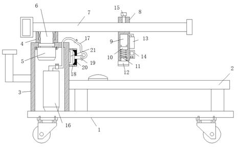
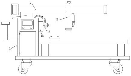
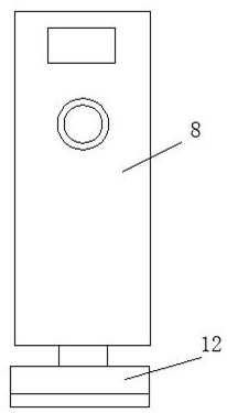
[0020] refer to Figure 1-3 , a kind of rescue device for emergency clinical cardiocerebral resuscitation, comprising a mobile seat 1, a bed body 2 and an installation box 3 are fixed on the mobile seat 1, the bed body 2 is located on the right side of the installation box 3, and a vertical shaft is fixed on the top of the installation box 3 To the bearing seat 4, and the top inner wall of the installation box 3 is fixed with a drive motor 5, the output end of the drive motor 5 is fixed with a rotating rod 6 that is installed in the bearing seat 4, and the upper end of the rotating rod 6 is fixed with a horizontal position The cross bar 7 above the bed body 2, the cr...


PUM


Abstract

The invention discloses an emergency clinical cardio-cerebral resuscitation rescue device, and relates to the field of medical instruments. The emergency clinical cardio-cerebral resuscitation rescuedevice comprises a moving seat; a bed body and a mounting box are fixed on the moving seat; the bed body is located on the right side of the mounting box; a vertical bearing seat is fixed at the top of the mounting box; a driving motor is fixed on the inner wall of the top of the mounting box; a rotating rod rotationally mounted in a bearing seat is fixed to the output end of the driving motor; atransverse rod transversely located above the bed body is fixed to the upper end of the rotating rod; the transverse rod is slidably sleeved with a movable block; a mounting cavity is formed in the lower end of the movable block; and a piston is arranged in the mounting cavity in a sliding fit mode. The rescue device not only can be used for rescue work, but also can easily perform cardiac resuscitation, so that the heart does not need to be manually pressed, and the use effect is good; the arranged movable block can transversely move to adjust the position; and meanwhile, the device can turnto one side when needed, so that a patient is not disturbed to get in and out of bed, the use effect is good, and the use is flexible.

Description

technical field [0001] The invention relates to the field of medical equipment, in particular to a cardiocerebral resuscitation rescue device for emergency clinical use. Background technique [0002] At present, when emergency patients undergo cardiocerebral resuscitation, they need to resuscitate the heart, chest and abdomen strongly. In the past, the rescue method was to use the cardiac resuscitation pump for uninterrupted compression, which required uninterrupted strong compression, and generally required experienced and skilled personnel. Technology can carry out effective rescue, and it is easy to control the intensity of compression, resulting in a decrease in the success rate of first aid and secondary injury to the patient's body. Moreover, the use of artificial cardiopulmonary resuscitation requires a lot of physical strength of medical staff, and it has a great impact on the level of physicians. The requirements are relatively high, and in the long run, it has grea...

Claims


Application Information

Patent Timeline
IPC IPC(8): A61H31/00A61M16/06A61L2/10
CPCA61H31/006A61L2/10A61M16/06
Inventor 岳超慧
Owner 岳超慧
Learn More