Bayonet lock fixing mode and fixing method for air respirator back plate device

A fixed method and respirator technology, applied in the direction of respiratory protection devices, life-saving equipment, etc., can solve the problems of changing the size and sliding of the main backplane and movable backplane

Inactive Publication Date: 2021-02-02
NANJING YAOZE ELECTRONICS TECH
View PDF7 Cites 0 Cited by
  • Summary
  • Abstract
  • Description
  • Claims
  • Application Information

AI Technical Summary

Problems solved by technology

[0004] However, the existing backboard telescopic devices basically use the screw fixing method. Since the waist hole has a predetermined length, when the screws and nuts inserted into the waist hole are not tightened, it is easy to cause the main backboard and the main backboard in the backboard device telescopic device to move. The sliding phenomenon of the backboard along the waist hole changes the size formed between the main backboard and the movable backboard

Method used


Image

  • Bayonet lock fixing mode and fixing method for air respirator back plate device
  • Bayonet lock fixing mode and fixing method for air respirator back plate device
  • Bayonet lock fixing mode and fixing method for air respirator back plate device

Examples


specific Embodiment approach 1

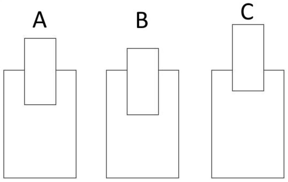
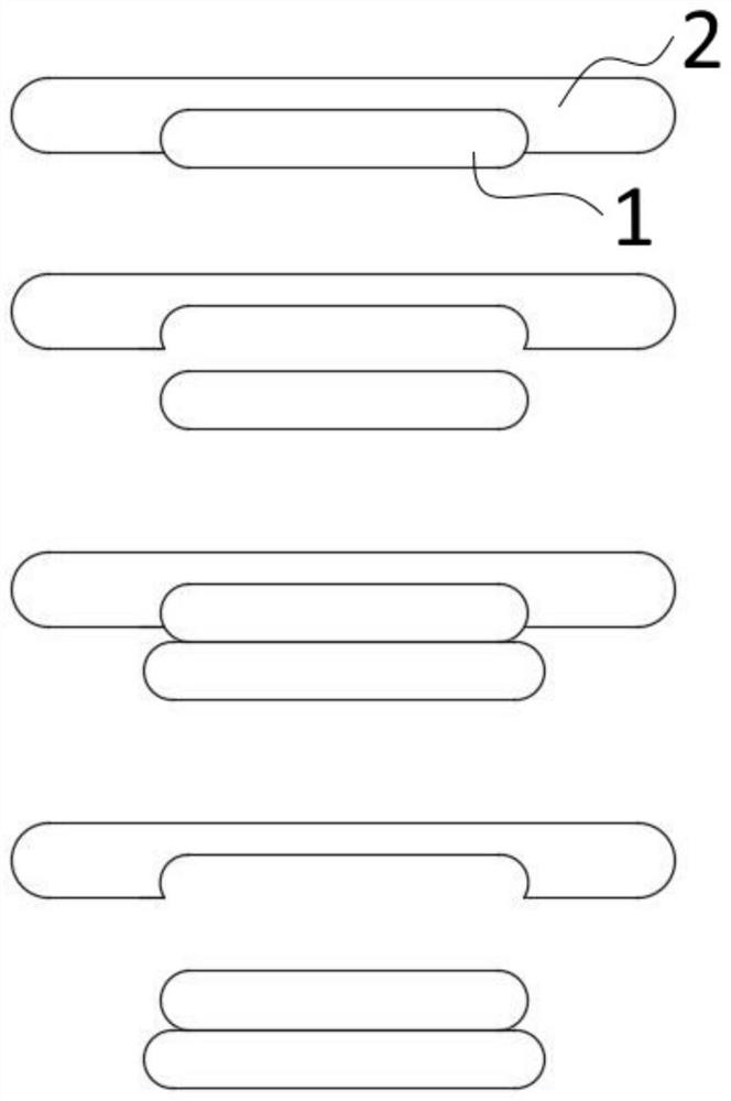
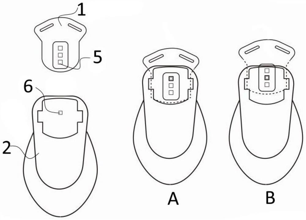
[0035] Embodiment 1: The single-hole bayonet fixing method includes setting a single limit hole 5 on the main backplane 2, and the movable backplane 1 is provided with a single row of limit holes 6; the single row of limit holes 6 The direction is parallel to the moving direction of the movable backplane 1, image 3 Accompanying drawings A and B are the expansion and contraction state diagrams of the expansion device of this embodiment.

specific Embodiment approach 2

[0036] Embodiment 2: The single-hole bayonet fixing method can also be provided with a single row of limiting holes 6 on the main backplane 2, and the movable backplane 1 is provided with a single limiting hole 5; the single row of limiting holes 6 The direction is parallel to the moving direction of the movable backplane 1, Figure 4 Accompanying drawings A and B are the expansion and contraction state diagrams of the expansion device of this embodiment.

[0037] Specific Embodiments 1 and 2: When the lengths of the two backplanes are adjusted in the U-shaped groove, at a certain position, the limit holes between the main backplane 2 and the movable backplane 1 will overlap. Use the bayonet to pass through the two overlapping holes. At this time, the two backplanes will not be able to slide in the U-shaped slot. The bayonet has an anti-falling function. It can be a pin, a screw, or an elastic buckle. The buckle is removed from the hole of either the main backplane 2 or the r...

specific Embodiment approach 3

[0038]Specific embodiment three: the double-hole bayonet fixing includes a single row of limiting holes 6 on both sides of the main backplane 2, and a single row of limiting holes 5 on both sides of the movable backplane 1; The direction of the row of limiting holes 6 is parallel to the moving direction of the movable backplane 1; the single limiting hole 5 is arranged at least three quarters of the movable backplane 1, and two limiting holes are used to align the main backplane. 2 The fixation with the movable backplane 1 can reduce the shaking phenomenon of the movable backplane 1 compared with the single-hole bayonet fixing method, Figure 5 Accompanying drawings A and B are the expansion and contraction state diagrams of the expansion device of this embodiment.


PUM


Abstract

The invention discloses a bayonet lock fixing mode and a fixing method for an air respirator back plate device. The bayonet lock fixing mode for the air respirator back plate device comprises main back plates and movable back plates movably connected with the main back plates, wherein U-shaped clamping grooves are formed in the faces, making contact with the movable back plates, of the main back plates, fastening devices are arranged between the main back plates and the movable back plates, and the fastening devices adopt the bayonet lock fixing mode and an elastic buckle fixing mode. According to the bayonet lock fixing mode for the air respirator back plate device, a screw fixing mode is replaced with the bayonet lock fixing mode and the elastic buckle fixing mode, and therefore the phenomenon that the main back plates and the movable back plates in a telescopic device of the back plate device slide along kidney-shaped holes easily when screws and nuts are not screwed, so that the size formed between the main back plates and the movable back plates is changed is avoided.

Description

technical field [0001] The invention relates to a backboard device of an air respirator, in particular to a bayonet fixing method for the backboard device of an air respirator, belonging to the security field. Background technique [0002] The respirator is a self-contained open-air respirator, widely used in firefighting, chemical industry, shipbuilding, petroleum, smelting, warehouses, laboratories, mines and other departments, for firefighters or emergency rescue personnel It can safely and effectively carry out fire extinguishing, emergency rescue and rescue work in various environments such as oxygen and oxygen. [0003] In high-risk operations such as fire rescue, emergency rescue, and industrial sites, operators need to use air respirators to ensure safety during operations. When operators enter the scene, the air respirators on their backs are usually carried on the backboard device. [0004] However, the existing backboard telescopic devices basically use the screw...

Claims


Application Information

Patent Timeline
IPC IPC(8): A62B9/00
CPCA62B9/00
Inventor 汤凯苏亚兵续欣
Owner NANJING YAOZE ELECTRONICS TECH
Why Eureka
Try Eureka