
One-by-one automatic feeding device and feeding method for strip-shaped revolving body workpieces

A technology of automatic feeding and revolving body, applied in the direction of rotary conveyor, conveyor control device, vibrating conveyor, etc., can solve the problems of low efficiency, high cost, difficult to realize automatic feeding, etc., to improve the degree of automation, Stable and reliable installation

Active Publication Date: 2021-02-02
HANGZHOU DIANZI UNIV
View PDF11 Cites 4 Cited by
  • Summary
  • Abstract
  • Description
  • Claims
  • Application Information

AI Technical Summary

Problems solved by technology

[0002] Bar-shaped rotary workpieces are the general term for straight rotary workpieces, including bolts, sleeves, bearing cylindrical rollers, etc. Bar-shaped rotary workpieces are often stacked and transported together in disorder after production, which is difficult for automatic use. To achieve automatic loading, it is often necessary to manually arrange them into a matrix, and then use industrial robots to automatically load the materials, which is costly and inefficient

Method used


Image

  • One-by-one automatic feeding device and feeding method for strip-shaped revolving body workpieces
  • One-by-one automatic feeding device and feeding method for strip-shaped revolving body workpieces
  • One-by-one automatic feeding device and feeding method for strip-shaped revolving body workpieces

Examples


Embodiment 1

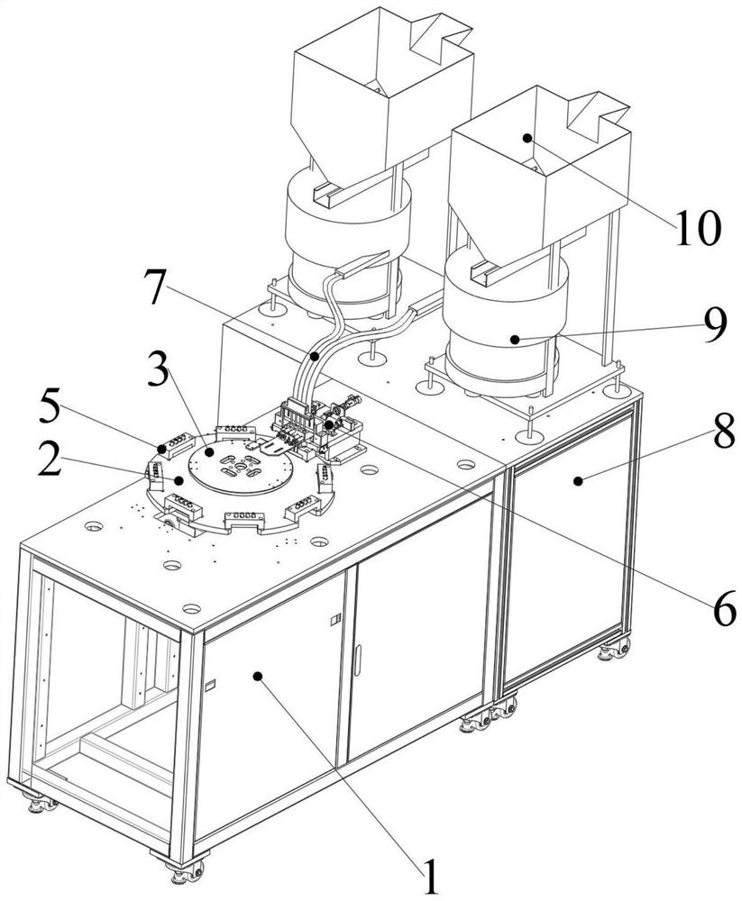
[0030] Such as figure 1 As shown, a bar-shaped rotary workpiece automatic feeding device one by one, including a vibrating plate feeding mechanism, a feeding circular tube 7 and a separate feeding mechanism arranged side by side. The vibrating plate conveying mechanism includes a conveying base 8 , a vibrating plate 9 and a storage funnel 10 . There are two vibrating disks 9. Two vibrating discs 9 are all installed on the charging base 18 . Each vibrating plate 9 has two workpiece output ports. A storage funnel 10 is arranged above the vibration plate 9 . The storage funnel 10 is fixed to the feeding base 18 . The loaded workpieces are stacked in the storage funnel 10 and the vibrating plate 9 .

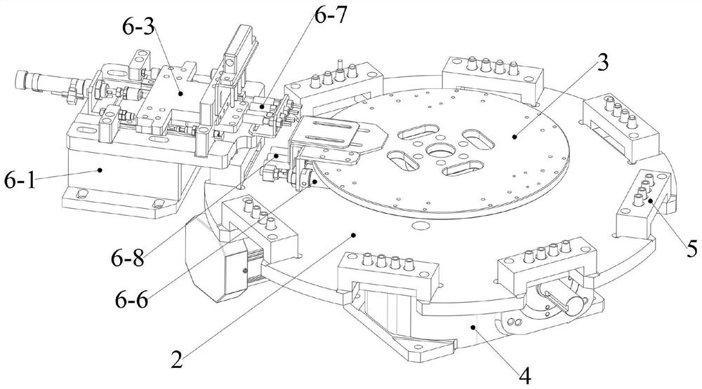
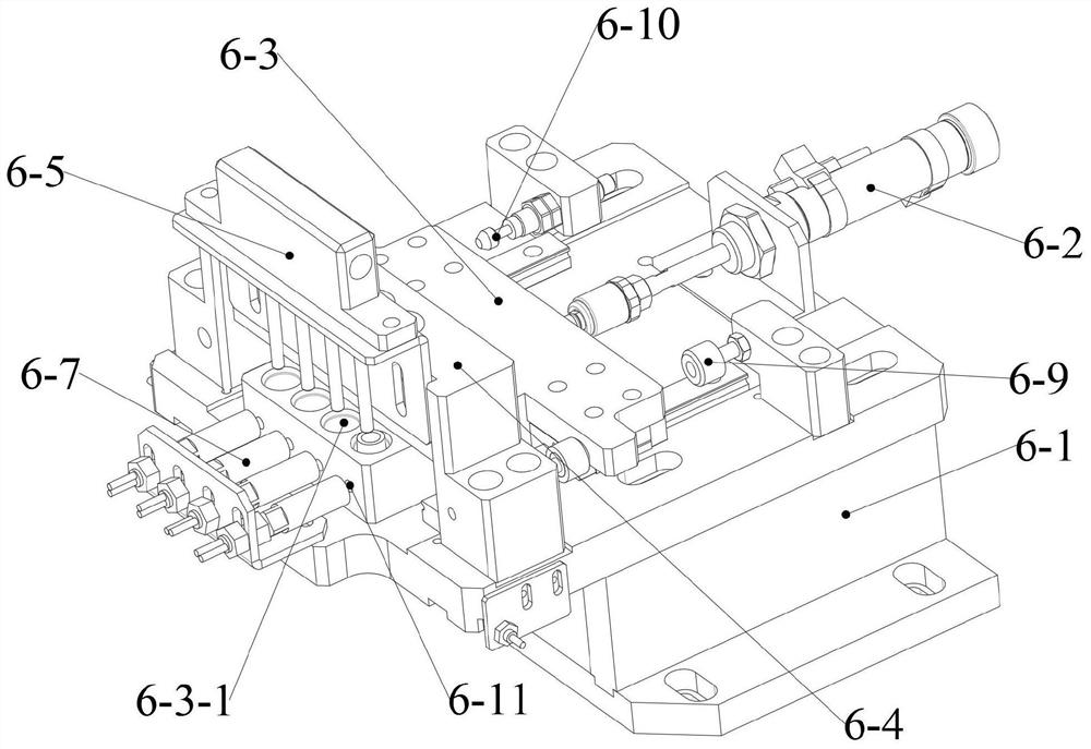
[0031] Such as figure 2 , 3 As shown in and 4, the separation feeding mechanism includes a feeding base 1, a switching turntable 2, a central fixed disk 3, a switching drive element 4, a workpiece storage block 5 and a feeding mechanism 6 one by one. The switching drive elem...

Embodiment 2

[0043] The difference between this embodiment and Embodiment 1 is that each workpiece storage block 5 does not adjust its position by switching the turntable, but adjusts its position by a conveyor belt.


PUM


Abstract

The invention discloses a one-by-one automatic feeding device and feeding method for strip-shaped revolving body workpieces. The strip-shaped revolving body workpieces are often stacked together disorderly to be transported after being produced, and automatic feeding is difficult to achieve during automatic use. The one-by-one automatic feeding device for the strip-shaped revolving body workpiecescomprises a vibration disc conveying mechanism, a conveying circular pipe and a separation feeding mechanism which are arranged side by side; and n material output ports of the vibration disc conveying mechanism continuously output the workpieces one by one through a vibration disc. The one-by-one feeding mechanism is installed on a feeding base, and comprises a sliding frame, a feeding power element, a sliding plate and a feeding block. The workpieces are automatically conveyed into the one-by-one feeding mechanism through the vibration disc and a pipeline; and then through reciprocating sliding of the sliding plate and mutual cooperation of a feeding hole in the feeding block, a transition hole in the sliding plate and a discharging hole in the sliding frame, the function that the workpieces sequentially arranged in the pipeline are separated to a workpiece storage block one by one is achieved, so that subsequent automated production is facilitated.

Description

technical field [0001] The invention belongs to the technical field of automatic feeding equipment, and in particular relates to an automatic feeding device and a feeding method for strip-shaped rotary workpieces one by one. Background technique [0002] Bar-shaped rotary workpieces are the general term for straight rotary workpieces, including bolts, sleeves, bearing cylindrical rollers, etc. Bar-shaped rotary workpieces are often stacked and transported together in disorder after production, which is difficult for automatic use. To achieve automatic feeding, it is often necessary to manually arrange them into a matrix, and then use industrial robots to automatically load the materials, which is costly and inefficient. Contents of the invention [0003] The object of the present invention is to provide an automatic feeding device and a feeding method for strip-shaped rotary workpieces one by one. [0004] The invention relates to a device for automatically feeding strip-...

Claims


Application Information

Patent Timeline
Patent Type & Authority Applications(China)
IPC IPC(8): B65G47/14B65G43/08B65G27/18B65G29/00B65G47/18B65G47/30
CPCB65G47/1421B65G43/08B65G27/18B65G29/00B65G47/18B65G47/30B65G2203/044
Inventor 王勇
Owner HANGZHOU DIANZI UNIV
Learn More