Eureka AIR delivers breakthrough ideas for toughest innovation challenges, trusted by R&D personnel around the world.

Safety management mechanism of industrial host guard

A security management and host technology, applied in the direction of electrical digital data processing, digital processing power distribution, digital data processing components, etc., can solve the problems of slow installation and disassembly

Inactive Publication Date: 2021-02-02
西安卓茂智能信息有限公司
View PDF1 Cites 0 Cited by
  • Summary
  • Abstract
  • Description
  • Claims
  • Application Information

AI Technical Summary

Problems solved by technology

[0006] The purpose of the present invention is to solve the problem that the installation and disassembly speed of the industrial host is too slow in the prior art by means of bolt locking, and proposes a safety management mechanism for the guard of the industrial host

Method used


Image

  • Safety management mechanism of industrial host guard
  • Safety management mechanism of industrial host guard
  • Safety management mechanism of industrial host guard

Examples


Embodiment 1

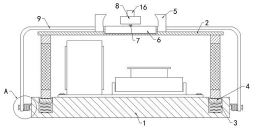
[0025]Example 1figure 1 As shown, the safety management mechanism of this industrial host guard includes a base plate 1 and a machine cover 2. The top of the base plate 1 is provided with an annular groove, and both ends of the inner surface of the annular groove are fixed with first springs 3, two The top of the first spring 3 is jointly fixed with an annular plate 4, the annular plate 4 is in contact with the groove wall of the annular groove, and the cover 2 is in contact with the top of the annular plate 4, and the bottom is located in the annular groove. The position of the cover 2 is initially determined. The top of the cover 2 is fixed with two symmetrical vertical plates 5, the top of the cover 2 is provided with two symmetrical limit slots, and the outer ends of the cover 2 are equipped with elastic In the limiting mechanism, the groove wall of the limiting slot contacts and connects with the limiting block 6, the top of the limiting block 6 is provided with a circular plat...

Embodiment 2

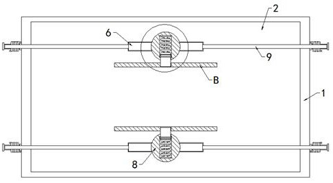
[0026]Example 2 is based on Example 1 asFigure 1-2 As shown, the top of its limit block 6 is rotatably connected with a rotating rod 7 through a second rotating bearing, and the top of the rotating rod 7 is fixedly connected to the top of the circular plate 8. The rotating rod 7 makes the circular plate 8 available in the limit block. The top of the 6 is easily rotated.

Embodiment 3

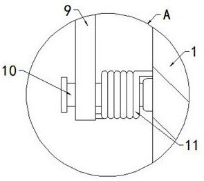
[0027]Example 3 is based on Example 1 asFigure 1-3 As shown, its elastic limit mechanism includes a U-shaped rod 9. Both sides of the base plate 1 are rotatably connected with a cross rod 10 through a second rotating bearing. The bottom ends of the U-shaped rod 9 and the rod walls of the two cross rods 10 A torsion spring 11 is sleeved on the rod wall of the cross bar 10, two ends of the torsion spring 11 are respectively fixedly connected with the U-shaped rod 9 and the base plate 1, and the top of the U-shaped rod 9 of the limit block 6 is fixedly sleeved.


PUM


Abstract

The invention relates to the technical field of industrial hosts, and discloses an industrial host guard safety management mechanism, which comprises a base plate and a cover, an annular groove is formed in the top of the base plate, first springs are fixedly arranged at the two ends of the bottom of the inner surface of the annular groove, an annular plate is jointly and fixedly arranged at the tops of the two first springs, the annular plate is in contact connection with the groove wall of the annular groove, the machine cover is in contact connection with the top of the annular plate, the bottom of the machine cover is located in the annular groove, two symmetrical vertical plates are fixedly arranged at the top of the machine cover, two symmetrical limiting grooves are formed in the top of the machine cover, elastic limiting mechanisms are arranged at the two ends of the outer side of the machine cover, the groove walls of the limiting grooves contact and connect with a limiting block, a circular plate is arranged at the top of the limiting block, an adjusting groove is formed in the top of the circular plate, and an inserting mechanism is arranged in the adjusting groove. According to the invention, the host can be rapidly disassembled when safety guards and the like in the industrial host go wrong.

Description

Technical field[0001]The invention relates to the technical field of industrial mainframes, in particular to a safety management mechanism for industrial mainframe guards.Background technique[0002]Industrial mainframes are industrial control computers exclusively used by the industry. Its basic performance and compatibility are almost the same as commercial computers. In order to improve the operational safety of existing industrial mainframes, security guards are often installed inside the mainframe to perform Security.[0003]The patent number CN211349229U discloses an industrial computer host. The host includes a chassis and a bottom plate. One side of the chassis is fixedly connected with a side plate by screws. The top of the front of the chassis is provided with a data interface, and the bottom of the front of the chassis is provided with a heat dissipation hole. One side of the upper surface of the chassis is fixedly connected with a grip, the other side of the upper surface of...

Claims


Application Information

Patent Timeline
IPC IPC(8): G06F1/18
CPCG06F1/181
Inventor 张金宝
Owner 西安卓茂智能信息有限公司
Why Eureka
Eureka Blog
Learn More