
Seismograph shockproof device

A technology of anti-seismic devices and seismometers, applied in the direction of seismic signal receivers, etc., can solve problems such as displacement, jumping, and overturning of seismometers, and achieve the effect of ensuring normal operation

Pending Publication Date: 2021-02-05
中国地震台网中心
View PDF0 Cites 0 Cited by
  • Summary
  • Abstract
  • Description
  • Claims
  • Application Information

AI Technical Summary

Problems solved by technology

[0005] In order to solve the problem of obvious displacement, jumping, or even overturning of the seismometer when a large earthquake occurs, so that the seismometer system cannot operate normally after a large earthquake, the purpose of the present invention is to provide a seismometer shockproof device

Method used


Image

  • Seismograph shockproof device
  • Seismograph shockproof device
  • Seismograph shockproof device

Examples


Embodiment 1

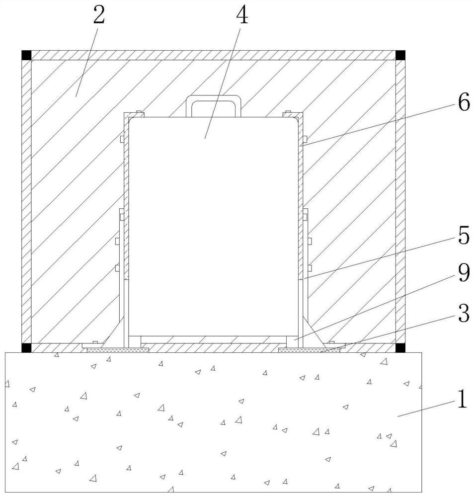
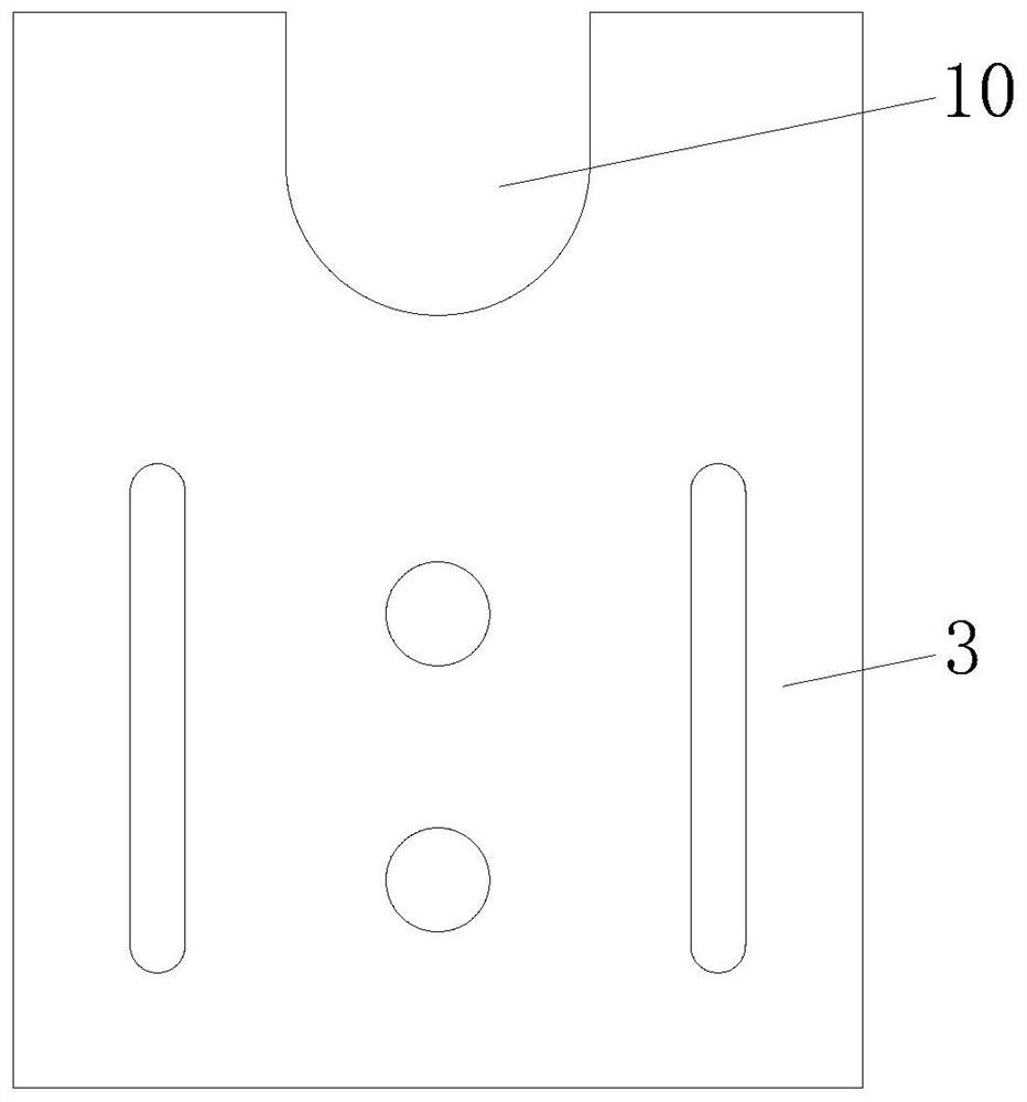
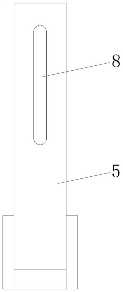
[0026] A kind of anti-shock device for a seismometer includes a seismic station 1, the base surface of the seismic station 1 is fixedly connected with a protective cover 2, and the base surface inside the protective cover 2 is fixedly connected with four base blocks 3 in an annular array, and The base surface between the four base blocks 3 is provided with a seismometer 4, the base surface of the base block 3 is fixedly connected with the limiting plate 5, and the outer wall of the seismometer 4 is fixedly connected with four connecting ring arrays. plate 6, the side wall of the connecting plate 6 is fixedly connected to the limiting column 7, the side wall of the connecting plate 6 is provided with a limiting hole 8, and the bottom of the seismometer 4 is fixedly provided with a leg 9.

[0027] The top of the protective cover 2 and the four side walls are provided with transparent glass.

[0028] The base block 3 and the seismic station 1 are connected by 955 structural adhes...

Embodiment 2

[0033] Seismic performance analysis of seismometer:

[0034] When the intensity of the seismic station is high, the seismometer will be displaced, which is a key problem that needs to be solved in the standardization of the station. The intensity of the seismic station (instrument pier surface) is related to the obtained ground peak acceleration, and there is friction between the placed seismometer and the instrument pier surface due to the self-weight factor. Assuming that the seismometer has a displacement S on the pier surface of the instrument, and the displacement is related to the self-weight m of the seismometer and the peak ground acceleration A obtained, the peak ground acceleration A is related to the square of the maximum peak frequency f and the maximum amplitude h of the passing seismic wave. Considering The influence of the friction coefficient factor between the placed seismometer and the pier surface of the instrument ([German] Valentin L. Popov, translated by ...


PUM


Abstract

The invention discloses a seismograph shockproof device which comprises a seismograph platform, wherein a protective cover is fixedly connected to the base surface of the seismograph platform, four base blocks are fixedly connected to the base surface located in the protective cover in an annular array mode, and seismographs are arranged on the base surface located among the four base blocks. A limiting plate is fixedly connected to the base surface of the base block, four connecting plates are fixedly connected to the outer wall of the seismometer in an annular array mode, limiting columns are fixedly connected to the side walls of the connecting plates, limiting holes are formed in the side walls of the connecting plates, and supporting legs are fixedly arranged at the bottom of the seismometer. The invention relates to the technical field of earthquake monitoring. According to the invention, the problem that the seismometer system cannot normally operate after being subjected to a large earthquake due to obvious displacement, jumping and even overturning of the seismometer in the case of the large earthquake is solved.

Description

technical field [0001] The invention relates to the technical field of earthquake monitoring, in particular to an anti-vibration device for a seismometer. Background technique [0002] Seismic stations are important places for monitoring work and the basic unit for earthquake monitoring, early warning, and forecasting. The standardization and standardization of station appearance and internal design is an important part of the construction of standardized seismic stations, and it has very important practical significance for promoting the informatization and modernization of earthquake prevention and disaster reduction business (Xiao Wujun et al., 2019). The standardized construction of stations puts forward the requirements of "shockproof reinforcement of instruments, standardized integrated wiring, and clear signs". Seismic reinforcement of seismic instruments is one of the important contents. The Design Atlas of Standardized Specifications for Seismic Stations (Revised D...

Claims


Application Information

Patent Timeline
Patent Type & Authority Applications(China)
IPC IPC(8): G01V1/18
CPCG01V1/18
Inventor 肖武军赵楠赵刚廖鹏张克诚
Owner 中国地震台网中心
Learn More