A dual-transistor forward converter with wide input voltage and high dynamic response
A forward converter, high dynamic technology, applied in the direction of converting DC power input to DC power output, output power conversion device, and adjusting electrical variables, etc., can solve the problem that the converter cannot have high dynamic response characteristics and cannot take advantage of all windings , the winding occupies a large space, etc., to achieve high dynamic response characteristics, improve efficiency, and reduce coil loss
- Summary
- Abstract
- Description
- Claims
- Application Information
AI Technical Summary
Problems solved by technology
Method used
Image
Examples
Embodiment 1
[0024] Overall structure of the present invention and overall working process of embodiment 1
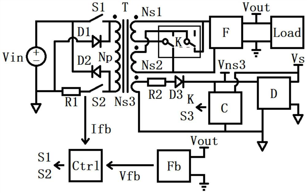
[0025] Such as figure 1 As shown, a double-transistor forward converter with wide input voltage and high dynamic response according to the present invention consists of main switches S1 and S2, diodes D1 and D2 for magnetic reset, current sampling resistor R1, transformer T, Double pole double throw relay K, output rectification filter circuit F, current limiting resistor R2, rectifier diode D3, auxiliary power supply circuit D, control circuit Ctrl, switching circuit C and feedback circuit Fb.
[0026]The on-off of the main switches S1 and S2 is controlled by the control circuit Ctrl. When the main switches S1 and S2 are turned on, the input voltage Vin is transformed by the transformer T, and the output voltage of the transformer T is smoothed by the output rectification filter circuit F to obtain the output voltage. Vout, the load Load is powered; when the main switches S1 and S...
Embodiment 2
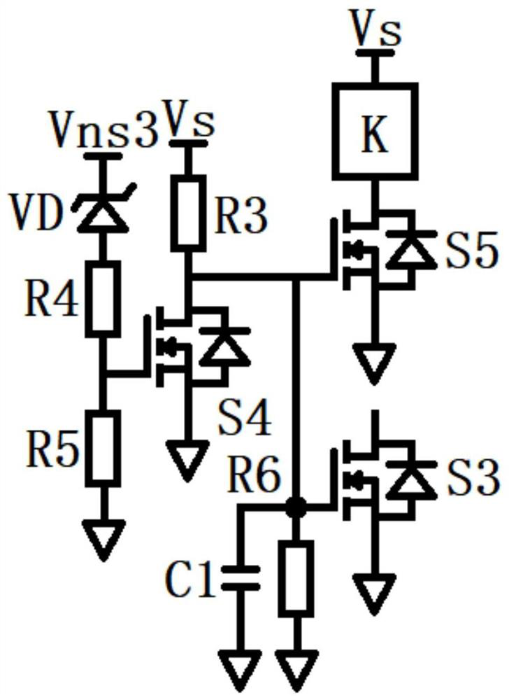
[0029] Embodiment 2 The specific structure and working principle of the switching circuit C of the present invention
[0030] Such as figure 2 As shown, the switching circuit C includes a Zener diode VD, resistors R3-R6, switching tubes S3-S5 and a capacitor C1, figure 2 K in is the double-pole double-throw relay K described in Embodiment 1. The DC voltage Vns3 is generated by the auxiliary power supply winding Ns3 and the auxiliary power supply circuit D, which indirectly reflects the size of the input network voltage Vin and then affects the switching circuit C to control the double-pole double-throw relay K to change the series-parallel connection of the secondary windings Ns1 and Ns2, The purpose of changing the turn ratio of the transformer T to adapt to the input voltage Vin is achieved.
[0031] When the input voltage Vin is high (220V), Vns3 is also high, the Zener diode VD is turned on, and the DC voltage Vns3 minus the conduction voltage drop of the Zener diode V...
Embodiment 3
[0033] Embodiment 3 The specific structure and working principle of the feedback circuit Fb of the present invention
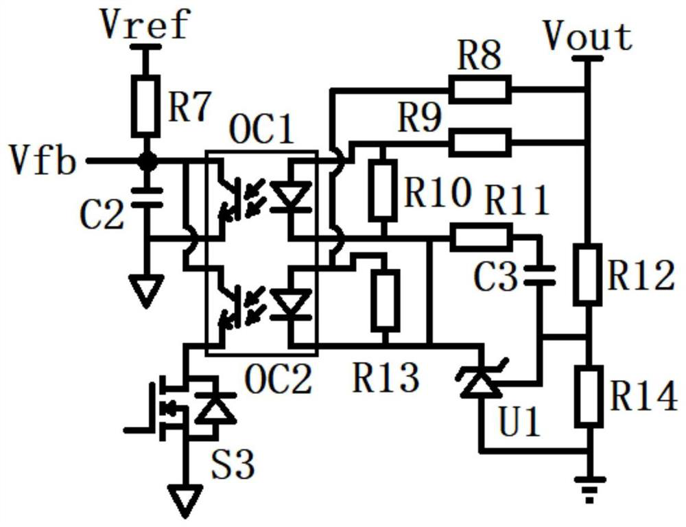
[0034] Such as image 3 As shown, the feedback circuit Fb includes resistors R7-R14, capacitors C2 and C3, optocouplers OC1 and OC2, and error amplifier U1, and S3 in the figure is the switch tube S3 described in Embodiment 2.
[0035] The voltage dividing resistors R12 and R14 divide the output voltage Vout of the output rectification and filtering circuit F, and then the error amplifier U1 amplifies the error voltage, and the amplified error voltage passes the error voltage to the optical through the resistors R8 and R9 and the optocouplers OC1 and OC2. Coupled output terminal Vfb, and then the error voltage is fed back to the control circuit Ctrl.
[0036] When the input terminals of the optocouplers OC1 and OC2 are not conducting, the resistors R10 and R13 provide an operating current to the error amplifier U1 to ensure that the error amplifier U1 can sta...
PUM
 Abstract
Description
Claims
Application Information
 - R&D
- Intellectual Property
- Life Sciences
- Materials
- Tech Scout
- Unparalleled Data Quality
- Higher Quality Content
- 60% Fewer Hallucinations
Browse by: Latest US Patents, China's latest patents, Technical Efficacy Thesaurus, Application Domain, Technology Topic, Popular Technical Reports.
© 2025 PatSnap. All rights reserved.Legal|Privacy policy|Modern Slavery Act Transparency Statement|Sitemap|About US| Contact US: help@patsnap.com


