Cylindrical workpiece surface printing device
A workpiece surface and printing device technology, applied in printing, printing machines, rotary printing machines, etc., can solve the problems of inability to flexibly adjust the parameters of cylindrical workpieces and not contain them, so as to save manpower and material costs, facilitate insertion and removal, The effect of reducing friction
- Summary
- Abstract
- Description
- Claims
- Application Information
AI Technical Summary
Problems solved by technology
Method used
Image
Examples
Embodiment 1
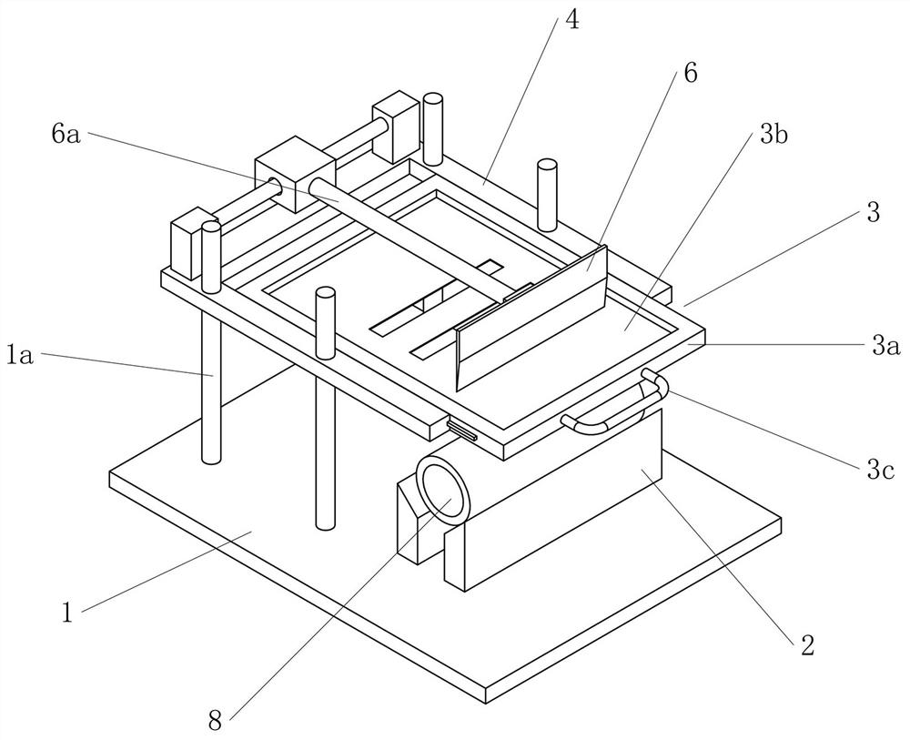
[0043] Embodiment 1: A cylindrical workpiece surface printing device includes a workbench 1 for installing other components, and the upper surface of the workbench 1 is installed with a positioning member group 2 for abutting against and fixing a cylindrical workpiece 8. The positioning component set 2 includes a plurality of positioning components. Specifically, the workbench 1 is provided with an adjustment slot, and the positioning member can move along the adjustment slot and is locked and fixed at this position by bolts and nuts; the support 2a included in the positioning member is upward The upper part of the support 2a is mounted with a roller 2b capable of rotating around a fixed axis relative to the support 2a. When the cylindrical workpiece 8 is erected on the positioning member group 2, the roller 2b can effectively reduce the frictional force received by the cylindrical workpiece 8 when it rotates, and at the same time, by adjusting the distance between the positio...
Embodiment 2
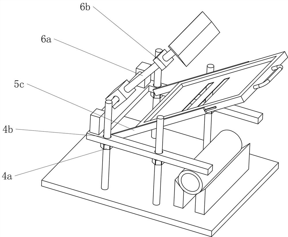
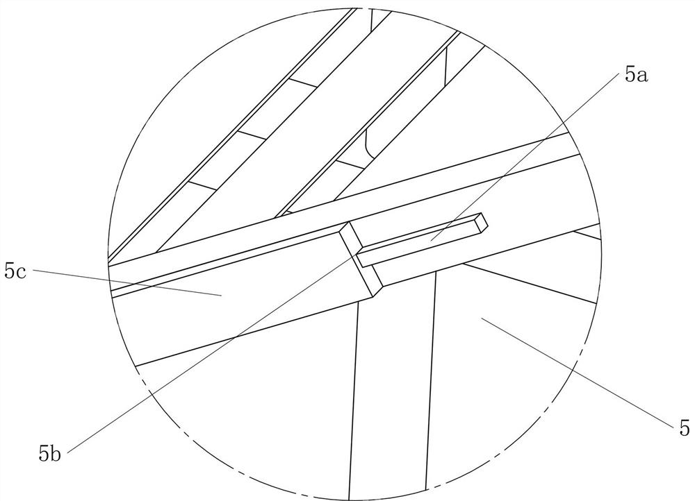
[0045] Embodiment 2: Improvement is made on the basis of the cylindrical workpiece surface printing device described in Embodiment 1. The guide support structure 4 also includes a pair of steering connecting rods 5c installed on both sides of the metal frame 3a. The inner end of the steering connecting rod 5c is connected to the guide support frame 4 through a hinged structure, and the inner surface of the steering connecting rod 5c and the metal frame 3a is provided with a snap-in outer surface for protruding outwards from both sides of the metal frame 3a. Guide groove 5b matched along 5a. When the printing mold plate 3 is installed on the steering connecting rod 5c through the cooperation structure of the clamping outer edge 5a and the guide groove 5b, the printing mold plate 3 can be realized to go around the hinges at both ends together with the steering connecting rod 5c. The axis of the cylinder rotates and lifts up at a certain angle to realize the opening of the cylind...
PUM
 Abstract
Description
Claims
Application Information
 - R&D
- Intellectual Property
- Life Sciences
- Materials
- Tech Scout
- Unparalleled Data Quality
- Higher Quality Content
- 60% Fewer Hallucinations
Browse by: Latest US Patents, China's latest patents, Technical Efficacy Thesaurus, Application Domain, Technology Topic, Popular Technical Reports.
© 2025 PatSnap. All rights reserved.Legal|Privacy policy|Modern Slavery Act Transparency Statement|Sitemap|About US| Contact US: help@patsnap.com


