
Automatic filling machine

A filling machine, automatic technology, applied in packaging, bottle filling, liquid bottling, etc., can solve problems such as not easy to drop, no fluidity, complex overall structure, etc., and achieve the effect of precise mixing amount

Pending Publication Date: 2021-02-09
GUANGDONG BAWEI BIOLOGICAL TECH CO LTD
View PDF0 Cites 0 Cited by
  • Summary
  • Abstract
  • Description
  • Claims
  • Application Information

AI Technical Summary

Problems solved by technology

The overall structure of the existing cosmetics filling equipment is relatively complicated, and it is mainly used for filling a single material, especially for oily mixed materials that are easy to agglomerate. This type of material is an oily mixture with almost no fluidity and is easy to agglomerate. Blocking, jamming, and sticking materials stick to equipment or contact parts and are not easy to fall. It is necessary to realize quantitative filling of multiple such mixtures at the same time to ensure that there is no mixing between each other, and each part is clear after filling. Stratification, so it is necessary to develop a filling machine that does not mix materials

Method used


Image

  • Automatic filling machine
  • Automatic filling machine
  • Automatic filling machine

Examples


Embodiment Construction

[0029] In order to make the purpose and technical solutions of the specific embodiments of the present invention clearer, the following will clearly and completely describe the technical solutions of the specific embodiments of the present invention in combination with the drawings and implementation examples of the specific embodiments of the present invention. Apparently, the described embodiments are some of the embodiments of the present invention, but not all of the embodiments.

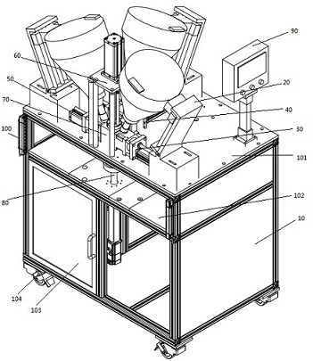
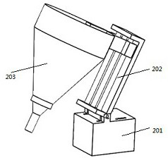
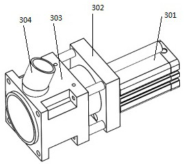
[0030] like figure 1 As shown, an automatic filling machine includes a frame 10. The frame 10 is divided into three layers. It is provided with an upper table 101, a lower table 102 and a cabinet 103 at the bottom, and also includes a filling mechanism installed on the upper table of the frame. 20. Pushing mechanism, pressing mechanism 60, distributing mechanism 70 and touch screen 90, supporting mechanism 80 installed on the lower table, pushing mechanism includes first pushing mechanism 30, se...


PUM


Abstract

The invention discloses an automatic filling machine, the automatic filling machine comprises a rack and further comprises filling mechanisms, pushing mechanisms, a pressing mechanism, a distributingmechanism and a supporting mechanism which are installed on the rack, the filling mechanisms are installed on the pushing mechanisms, the plurality of pushing mechanisms are arranged, the distributingmechanism is provided with a distributing cavity, the distributing cavity is provided with a plurality of cavities, a distributing conveying channel is arranged in the middle of the distributing cavity, the distributing conveying channel is provided with a plurality of channels, the pressing mechanism is installed on the rack and is arranged above the distributing mechanism and opposite to the distributing conveying channel, the bottom of the distributing mechanism right faces the top end of the supporting mechanism, a filling bottle can be placed at the top end of the supporting mechanism tobe in butt joint with the bottom of the distributing mechanism and used for receiving materials conveyed by the distributing conveying channel, and the filling mechanisms, the pushing mechanisms, thepressing mechanism and the supporting mechanism are all connected with a control box installed at the bottom of the rack. According to the automatic filling machine, quantitative filling of differentoil mixtures is achieved, and different mixed materials can be clearly layered and are not mixed with one another.

Description

technical field [0001] The invention relates to the technical field of cosmetic production equipment, in particular to an automatic filling machine. Background technique [0002] In the production process of cosmetics, the material needs to be filled after the production of the material is completed, and the quantitative material is filled into a container with a certain capacity. The overall structure of the existing cosmetics filling equipment is relatively complicated, and it is mainly used for filling a single material, especially for oily mixed materials that are easy to agglomerate. This type of material is an oily mixture with almost no fluidity and is easy to agglomerate. Blocking, jamming, and sticking materials stick to equipment or contact parts and are not easy to fall. It is necessary to realize quantitative filling of multiple such mixtures at the same time to ensure that there is no mixing between each other, and each part is clear after filling. Stratificati...

Claims


Application Information

Patent Timeline
Patent Type & Authority Applications(China)
IPC IPC(8): B67C3/02B67C3/22B67C3/28
CPCB67C3/02B67C3/22B67C3/28
Inventor 彭林胡顺陈清云崔运升
Owner GUANGDONG BAWEI BIOLOGICAL TECH CO LTD
Learn More