Stamping device for hardware stamping part

A technology of stamping device and stamping parts, which is applied in the direction of feeding device, positioning device, storage device, etc., can solve the problems of reducing the work efficiency of workers, increasing the labor intensity of workers, and the object is not easy to be demolded, so as to increase labor intensity and structure. Simple, innovative design effects

Inactive Publication Date: 2021-02-12
滁州市天鸿冲塑制品有限公司
View PDF0 Cites 6 Cited by
  • Summary
  • Abstract
  • Description
  • Claims
  • Application Information

AI Technical Summary

Problems solved by technology

[0003] The invention proposes a stamping device for metal stamping parts, which solves the problem that the existing stamping device is not easy to demould after stamping, and it needs to manually collect the stamped objects. The whole process is time-consuming and labor-intensive, which increases the labor of workers. strength, which reduces the work efficiency of workers

Method used


Image

  • Stamping device for hardware stamping part
  • Stamping device for hardware stamping part
  • Stamping device for hardware stamping part

Examples


Embodiment Construction

[0020] The following will clearly and completely describe the technical solutions in the embodiments of the present invention with reference to the accompanying drawings in the embodiments of the present invention. Obviously, the described embodiments are only some, not all, embodiments of the present invention.

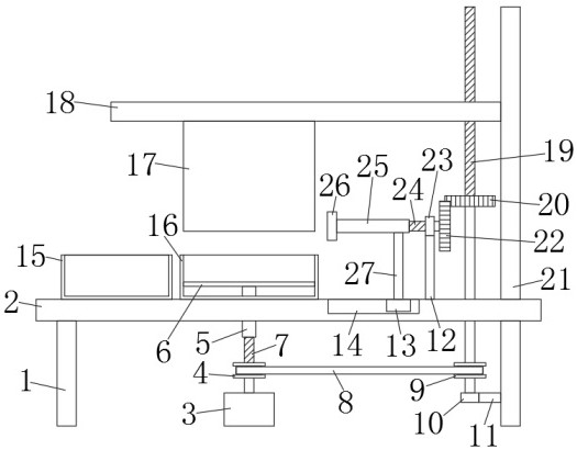
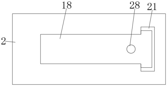
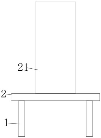
[0021] refer to Figure 1-3 , an embodiment provided by this solution: a stamping device for metal stamping parts, including a placement board 2, the bottom sides of the placement board 2 are fixedly connected with support columns 1, and the top right side of the placement board 2 is fixedly connected with a column 21 , The bottom of the placing plate 2 is provided with a driving mechanism, the top of the placing plate 2 is provided with a stamping mechanism, and the top of the placing plate 2 is provided with an automatic material receiving mechanism.

[0022] In this embodiment, the drive mechanism includes a drive motor 3 arranged directly below the placement plat...


PUM


Abstract

The invention discloses a stamping device for a hardware stamping part, and relates to the technical field of stamping devices. The stamping device aims at solving the problems that according to an existing stamping device, after stamping, an object is not prone to demolding, the stamped object needs to be collected manually, the whole process wastes time and labor, the labor intensity of workersis increased, and the working efficiency of the workers is reduced. According to the scheme, the stamping device comprises a placing plate, wherein supporting columns are fixedly connected to the twosides of the bottom of the placing plate, a stand column is fixedly connected to the right side of the top of the placing plate, a driving mechanism is arranged at the bottom of the placing plate, a stamping mechanism is arranged at the top of the placing plate, and an automatic material collecting mechanism is arranged at the top of the placing plate. The stamping device is novel in design, simple in structure and convenient to operate, the stamped object can be automatically demolded, the stamped object can be automatically collected, time and labor are saved in the whole process, the laborintensity of the workers is reduced, and the working efficiency of the workers is improved.

Description

technical field [0001] The invention relates to the technical field of stamping devices, in particular to a stamping device for metal stamping parts. Background technique [0002] The existing stamping device is not easy to demold the object after stamping, and it needs to manually collect the stamped objects. The whole process is time-consuming and laborious, which increases the labor intensity of workers and reduces the work efficiency of workers. Therefore, we propose- A stamping device for metal stamping parts. Contents of the invention [0003] The invention proposes a stamping device for metal stamping parts, which solves the problem that the existing stamping device is not easy to demould after stamping, and it needs to manually collect the stamped objects. The whole process is time-consuming and labor-intensive, which increases the labor of workers. Intensity, which reduces the work efficiency of workers. [0004] In order to achieve the above object, the present...

Claims


Application Information

Patent Timeline
Patent Type & Authority Applications(China)
IPC IPC(8): B21D22/02B21D45/02B21D43/20
CPCB21D22/02B21D43/20B21D45/02
Inventor 谢杰龙李进憬
Owner 滁州市天鸿冲塑制品有限公司
Why Eureka
Try Eureka