Heating/cooling device for a housing particularly for a throttle valve nozzle

A technology for cooling devices and throttle valves, applied in valve heating/cooling devices, fuel heat treatment devices, valve devices, etc., can solve the problems of heavy hose weight and high production cost, and achieve simplified installation and improved sealing reliability sexual effect

Inactive Publication Date: 2015-04-29
CONTINENTAL AUTOMOTIVE GMBH
View PDF7 Cites 0 Cited by
  • Summary
  • Abstract
  • Description
  • Claims
  • Application Information

AI Technical Summary

Problems solved by technology

[0003] The disadvantage of the known heating/cooling device is that the conne

Method used


Image

  • Heating/cooling device for a housing particularly for a throttle valve nozzle
  • Heating/cooling device for a housing particularly for a throttle valve nozzle
  • Heating/cooling device for a housing particularly for a throttle valve nozzle

Examples


Embodiment Construction

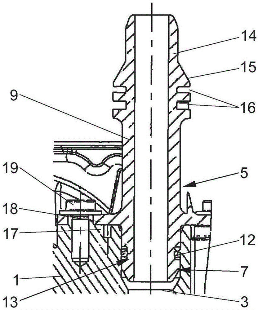
[0018] figure 1 The housing 1 of a throttle bushing of a motor vehicle internal combustion engine is shown. The housing 1 is designed as a sensor housing of a generally known drive of a throttle valve (not shown in detail) and has a heating / cooling device 2 with a channel 3 . The channel 3 is situated between the two connections 4 , 5 and serves for the passage of a heating or cooling medium for heating or cooling the housing 1 . The housing 1 has a receptacle 6 , 7 for each tube 8 , 9 . On one of the pipes 9 , for example a medium-carrying hose 10 is connected by means of a quick coupling 11 .

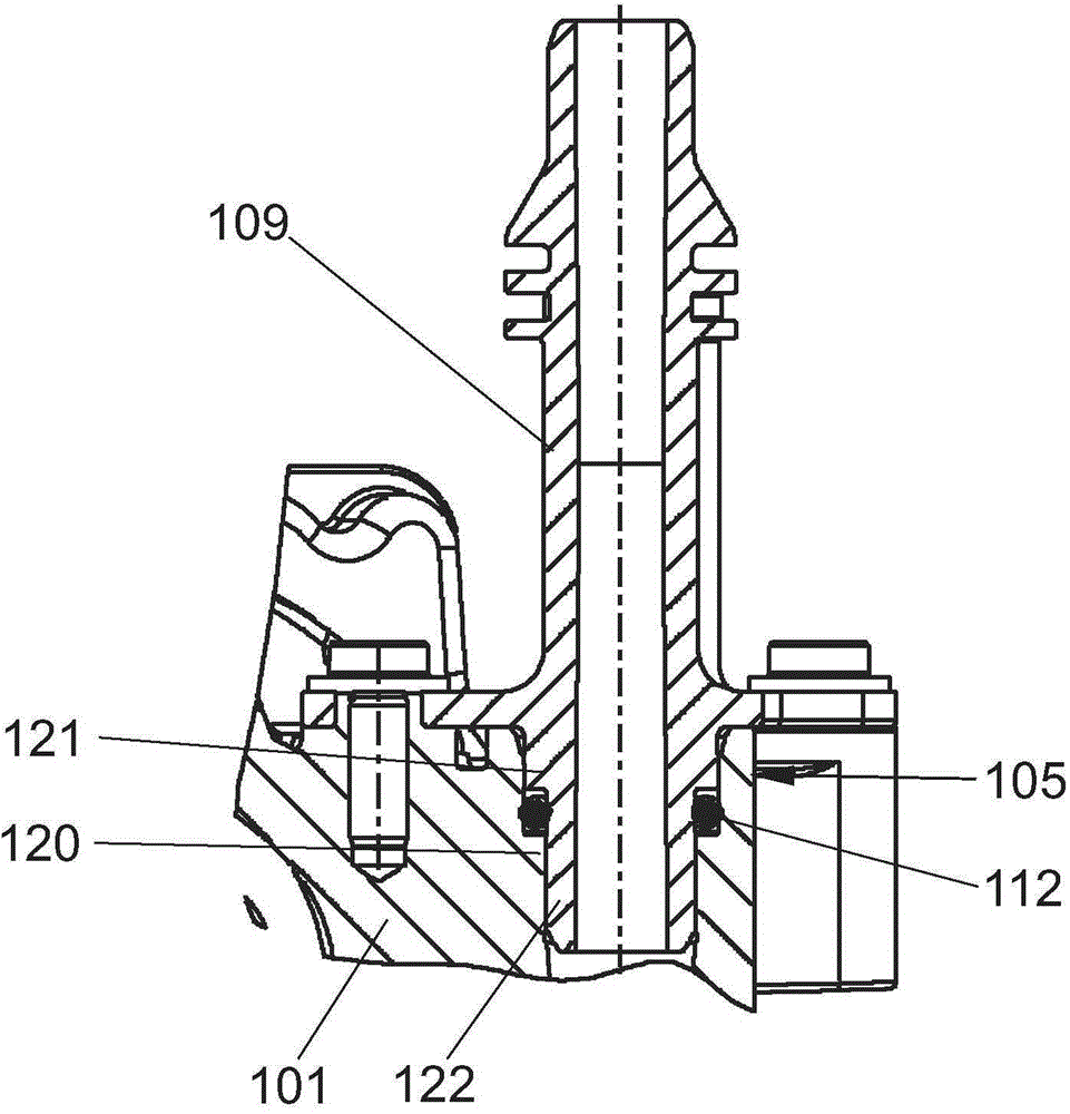
[0019] figure 2 greatly magnified showing the figure 1 Interface 5 in . It should be noted here that the tube 9 in the receptacle 7 is sealed by means of the sealing element 12 . The sealing element 12 is designed as a radially sealing O-ring and is arranged in a circumferential groove 13 of the tube 9 . The part of the tube 9 which protrudes beyond the housing 1 has a connect...


PUM


Abstract

A heating/cooling device (2) for a sensor housing (1) a throttle valve housing of an internal combustion engine has a pipe (9) connected with the passage (3) of a leading medium, manufactured from a plastics material, and detachably fixed in the housing (1). The tube (9) axially prestress against the housing (1) and is sealed radially with respect to this. Further, the tube (9) has a part of a quick coupling device (11) connected with a leading medium line (10).

Description

technical field [0001] The invention relates to a heating / cooling device for a housing, in particular for a throttle bushing of an internal combustion engine of a motor vehicle, having channels arranged in the housing for the passage of a heating or cooling medium, There is a tube connected to the channel, with a connecting sleeve arranged on the tube for connecting a medium-carrying hose to the channel. Background technique [0002] Heating / cooling devices are frequently used in components of motor vehicles that are to be thermally controlled, such as the sensor housing of a throttle valve bushing, and are known from practice. The housing, which should be thermally controlled, is mostly made of light metal. The two pipes for the inflow / outflow of the heating / cooling medium are mostly made of brass and are pressed into the housing. The hose that is to be connected to the channel is connected to this pipe by means of a hose clamp. [0003] The disadvantage of the known hea...

Claims


Application Information

Patent Timeline
IPC IPC(8): F01P11/04
CPCF02D9/1035F02D9/108F02M15/02F02M31/10F02M31/20F16K1/22F16K27/0218F16K49/005Y02T10/12
Inventor 托马斯·西佩尔西尔维乌·索普蒂卡
Owner CONTINENTAL AUTOMOTIVE GMBH
Why Eureka
Try Eureka