Automatic riveting device for electronic cigarette manufacturing

An electronic cigarette, riveting pressure technology, applied in the direction of manufacturing tools, tobacco, metal processing equipment, etc., can solve the problems of unfavorable enterprise production, high defective rate, high riveting pressure, etc., to facilitate cutting, ensure quality, and riveting pressure. uniform effect

Active Publication Date: 2021-02-12
东莞市拓伸电子科技有限公司
View PDF5 Cites 0 Cited by
  • Summary
  • Abstract
  • Description
  • Claims
  • Application Information

AI Technical Summary

Problems solved by technology

[0004] The original operation method of connecting the copper core and the sleeve is done by manpower, and the efficiency is low. At the same time, due to the high riveting pressure, the defective rate is high during riveting, which is not conducive to the production of enterprises.

Method used


Image

  • Automatic riveting device for electronic cigarette manufacturing
  • Automatic riveting device for electronic cigarette manufacturing
  • Automatic riveting device for electronic cigarette manufacturing

Examples


Embodiment 1

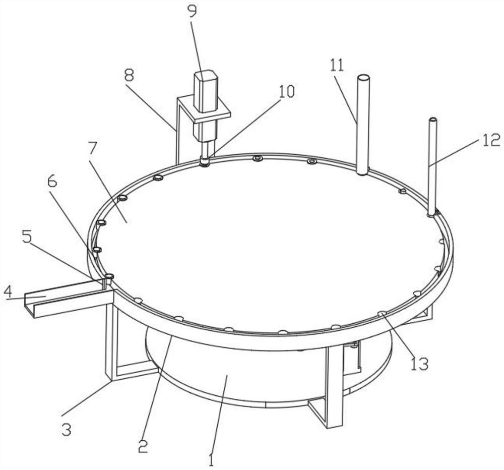
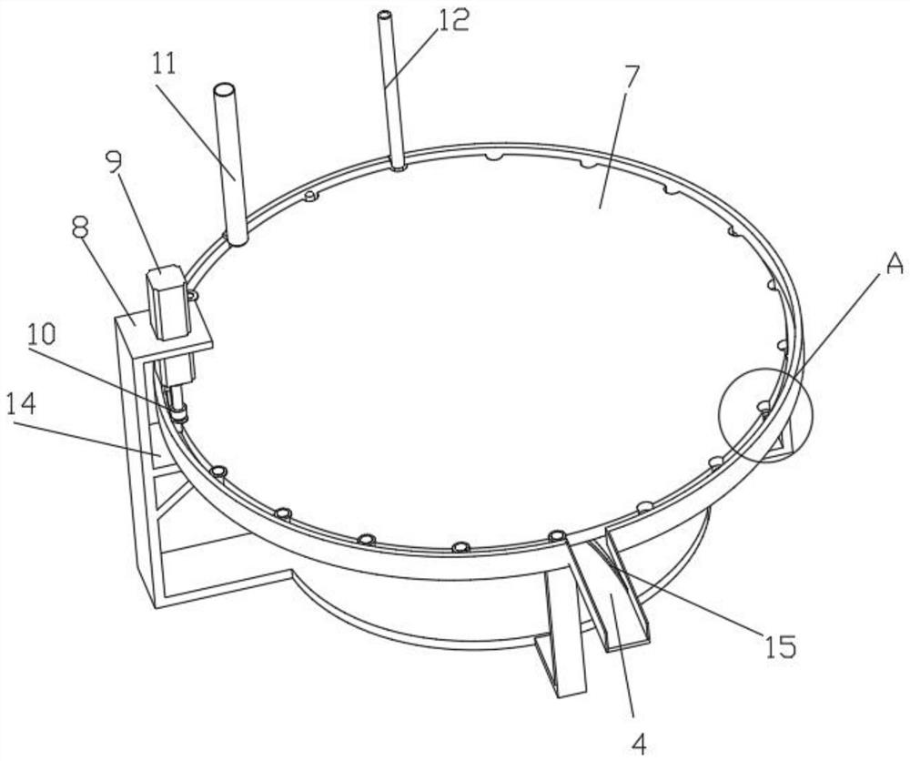
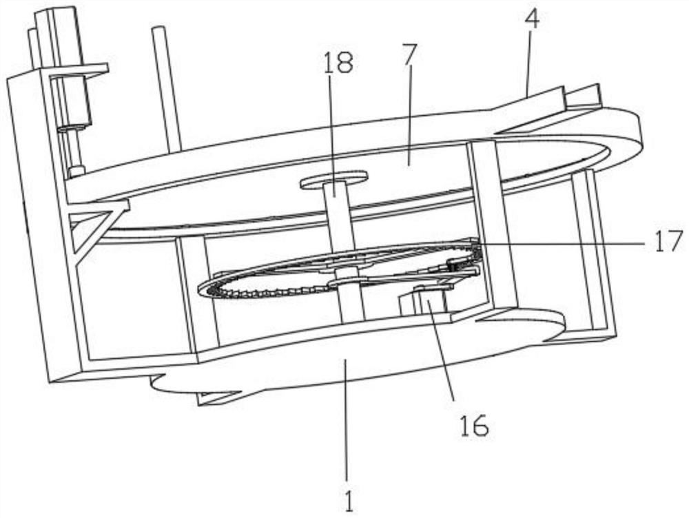
[0031] Such as figure 1 , 2 , an automatic riveting device for electronic cigarette manufacturing as shown in 3, 4, and 6, including a support plate 1, a copper core 30 and a sleeve 31, and the side wall of the support plate 1 is evenly fixed and connected with an L-shaped support along the circumferential direction Plate 3, the top of the L-shaped support plate 3 is fixedly connected with a support ring 6, the top of the support ring 6 is fixedly connected with a ring 2, and the left end of the ring 2 is provided with a discharge hole 5, and the ring 2 is at the discharge hole 5 A discharge U-shaped plate 4 for blanking is fixedly connected, the inner wall of the discharge U-shaped plate 4 is fixedly connected with an arc-shaped guide plate 15 for guiding the finished product to move into the discharge U-shaped plate 4, and the inner end of the arc-shaped guide plate 15 Fixedly connected with the top of the support ring 6, the arc-shaped guide plate 15 is convenient for movi...

Embodiment 2

[0034] Embodiment 2 is a further improvement to Embodiment 1.

[0035] Such as figure 1 , 5 The adjustment structure shown comprises a support arc plate 28 and an oblique guide plate 29, the support arc plate 28 and the oblique guide plate 29 are all fixedly installed on the top of the discharge U-shaped plate 4, and the oblique guide plate 29 is arranged on the support arc. The right end of the plate 28, when the copper core 30 is in contact with the inclined guide plate 29, pushes the top of the copper core 30 to move upwards and pushes the riveting position of the copper core 30 to move to the top of the sleeve 31, and 10 is set in the middle of the supporting arc plate 28. At the top of the end, because the top of the sleeve 31 is flush with the top of the copper core 30 to ensure that the copper core 30 slides normally under the sleeve feeding tube 11, the top of the copper core 30 needs to be adjusted to the top of the sleeve 31 when riveting. At the top, the sleeve 31...


PUM


Abstract

The invention discloses an automatic riveting device for electronic cigarette manufacturing, and relates to the technical field of electronic cigarette production. The automatic riveting device comprises a supporting plate, a copper core and a sleeve, L-shaped supporting plates are evenly and fixedly connected to the side wall of the supporting plate in the circumferential direction, a supportingring is fixedly connected to the tops of the L-shaped supporting plates, and a circular ring is fixedly connected to the top of the supporting ring; a discharging hole is formed in the left end of thecircular ring, a discharging U-shaped plate used for discharging is fixedly connected to the position, at the discharging hole, of the circular ring, a copper core discharging pipe used for discharging copper cores is fixedly connected to the right end of the circular ring, and a copper core discharging pipe is placed in the copper core discharging pipe; and the circular ring is fixedly connectedwith a sleeve discharging pipe in the anticlockwise direction of the copper core discharging pipe. The automatic riveting device has the advantages that the automatic riveting is realized, the efficiency is higher, meanwhile, the riveting pressure is uniform, the quality is ensured, and the enterprise production is facilitated.

Description

technical field [0001] The invention relates to the technical field of electronic cigarette production, in particular to an automatic riveting device for electronic cigarette production. Background technique [0002] E-cigarettes are electronic products that mimic cigarettes and have the same look, smoke, taste and feel as cigarettes. It is a product that allows users to inhale after turning nicotine, etc. into steam by means of atomization. The World Health Organization conducted research on e-cigarettes and came to a clear conclusion: e-cigarettes are harmful to public health, and it is not a means of quitting smoking. It is necessary to strengthen its control to prevent harm to young people and non-smokers. [0003] The electronic cigarette core is the core component of the electronic cigarette. It is mainly composed of a sleeve, a copper core and a spiral heating wire. The end is plugged in, and finally the copper core and the sleeve are firmly connected together by ri...

Claims


Application Information

Patent Timeline
Patent Type & Authority Applications(China)
IPC IPC(8): B23P19/027A24F40/70
CPCB23P19/027A24F40/70
Inventor 胡桃莉何琛王耸霄何友根何产军
Owner 东莞市拓伸电子科技有限公司
Why Eureka
Try Eureka