A profile matching laying method for heat insulation layer

A heat insulation layer and surface matching technology, which is applied in the field of heat insulation layer surface matching laying, can solve the problems of heat insulation layer surface complexity limitation, limited curing area, uneven force, etc., and achieve surface flatness Good, good workmanship, guarantee the effect of heat insulation effect

Active Publication Date: 2022-05-06
AEROSPACE INST OF ADVANCED MATERIALS & PROCESSING TECH
View PDF5 Cites 0 Cited by
  • Summary
  • Abstract
  • Description
  • Claims
  • Application Information

AI Technical Summary

Problems solved by technology

[0006] The technical problem to be solved by the present invention is that the traditional heat insulation layer bonding and curing method has limited curing area, limited complexity of the bonded heat insulation layer surface, uneven force, prone to cracks, damage, etc.

Method used


Image

  • A profile matching laying method for heat insulation layer
  • A profile matching laying method for heat insulation layer
  • A profile matching laying method for heat insulation layer

Examples


Embodiment 1

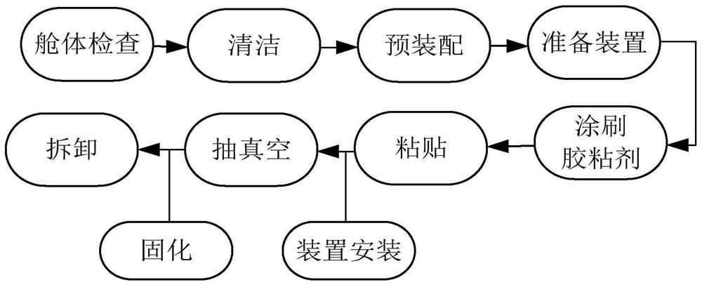
[0043] In this embodiment, a single inner insulation layer is used to lay the cabin body, and the specific operations are as follows:

[0044] (1) Check the cabin body that needs to be laid with heat insulation layer, including structural integrity, wall flatness, etc. The volume of the cabin body is 0.8m 3 ; It is judged that the cabin and the heat insulation layer can be integrally installed in the vacuum auxiliary device, and the heat insulation layer can be laid;

[0045] (2) Clean the cabin body where the heat insulation layer needs to be laid, and ensure that the contact surface between the heat insulation layer and the cabin body is clean and free of oil stains;

[0046] (3) Prepare the single-block inner heat-insulation layer that needs to be laid, and the heat-insulation layer is made of flexible heat-insulation material, and then this heat-insulation layer and the cabin body are preassembled;

[0047] (4) Make a vacuum auxiliary device according to the size, shape a...

Embodiment 2

[0054] In this embodiment, 6 inner insulation layers are used to lay the cabin body, and the specific operations are as follows:

[0055] (1) Check the cabin body that needs to be laid with heat insulation layer, including structural integrity, wall flatness, etc. The volume of the cabin body is 2m 3 ; It is judged that the structure of the cabin can be used as a part of the vacuum auxiliary device, and the heat insulation layer can be laid;

[0056] (2) Clean the cabin body where the heat insulation layer needs to be laid, and ensure that the contact surface between the heat insulation layer and the cabin body is clean and free of oil stains;

[0057] (3) Prepare 6 inner heat insulation layers that need to be laid, and the heat insulation layer is made of flexible heat insulation material, and then the heat insulation layer and the cabin body are preassembled;

[0058] (4) Make a vacuum auxiliary device according to the size, shape and tightness of the cabin;

[0059] (5) App...

Embodiment 3

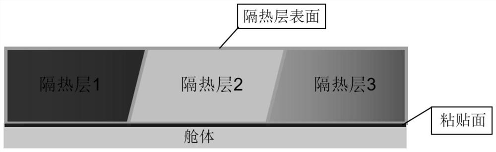
[0065] It is carried out in the same manner as in Example 1, except that the heat insulation layer is an outer heat insulation layer.

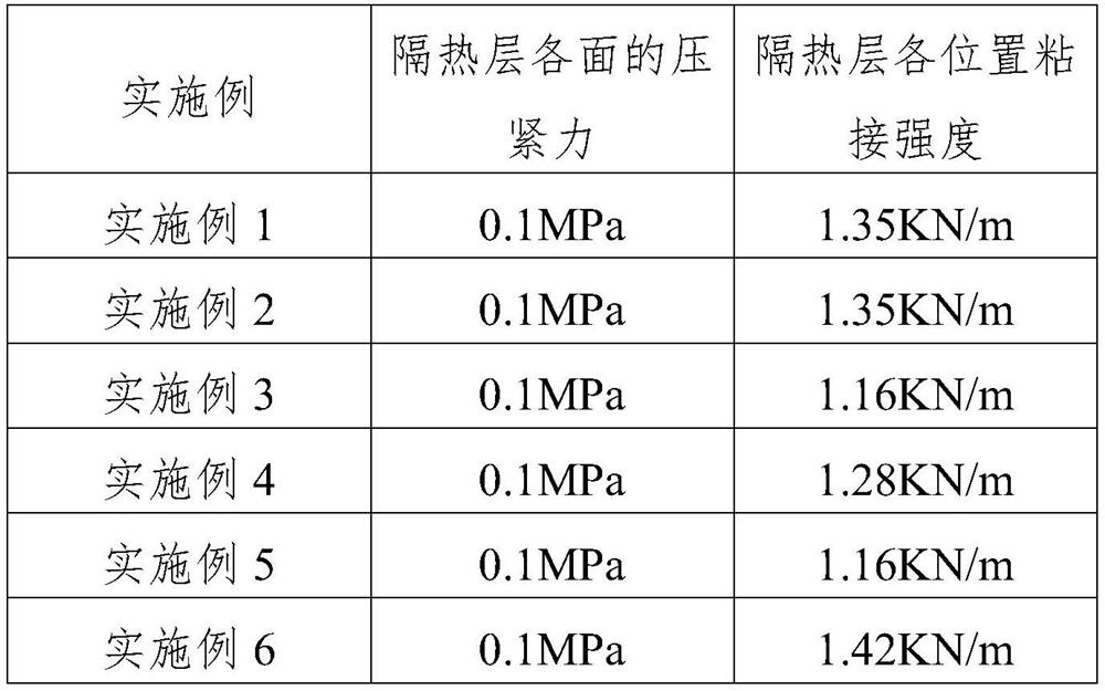
[0066] After testing, the compression force on each side of the heat insulation layer during the curing process and the bonding strength of each position of the heat insulation layer after curing are shown in Table 1.


PUM


Abstract

The invention relates to a profile-matched laying method for a heat insulation layer. The laying method includes the following steps: (1) evenly applying adhesive on the contact surface between a single or multiple complex profile heat insulation layer and a cabin body, And put the heat insulation layer in its corresponding cabin body sticking position; (2) Make a vacuum auxiliary device according to the characteristics of the cabin body size, shape and sealing; (3) Use the prepared vacuum auxiliary device to paste the heat insulation layer And the cabin body is evacuated and pressure-cured. After the curing is completed, the vacuum auxiliary device is removed, thereby completing the matching laying of the complex heat insulation layer. The invention has simple process and strong operability, and the pasted heat insulation layer is evenly stressed during the curing process, can match the height of the profiles between the cabins, and is firmly pasted, so as to achieve good heat insulation effect.

Description

technical field [0001] The invention relates to the technical field of functional composite materials, in particular to the laying technology of a heat insulating layer, and in particular to a profile matching laying method for a heat insulating layer. Background technique [0002] With the rapid development of my country's aerospace technology, the heat insulation layer has become an indispensable part of the structure and thermal protection system. Its function is to effectively prevent heat from entering the interior of the cabin when the aircraft is flying quickly for a long time, so as to maintain a lower temperature in the cabin and ensure the normal operation of equipment and instruments. [0003] The traditional bonding and curing methods of the heat insulation layer mainly include: sandbag compaction method, tool clamp clamping method, tape winding and tightening method, etc. The disadvantages of the above method of bonding and curing are obvious: 1) The sandbag co...

Claims


Application Information

Patent Timeline
Patent Type & Authority Patents(China)
IPC IPC(8): B29C65/48B29C37/00B64F5/10
CPCB29C65/48B29C37/00B29C66/0222B64F5/10
Inventor 王军辉权成王子宁白莉娟黄娣杨洁颖张昊
Owner AEROSPACE INST OF ADVANCED MATERIALS & PROCESSING TECH
Why Eureka
Try Eureka