
Differential chain assembly line for bundling, loading and unloading

A technology of assembly line and differential chain, which is applied to the parts of strapping machinery, strapping materials, packaging, etc., and can solve problems such as downward bending

Inactive Publication Date: 2021-02-19
广州玛宝伦贸易有限公司
View PDF0 Cites 0 Cited by
  • Summary
  • Abstract
  • Description
  • Claims
  • Application Information

AI Technical Summary

Problems solved by technology

[0003] Since the strapping machine for the differential chain assembly line directly draws the packing strap to the bending frame through the strapping device and then tightens it on the packing box, if the packing strap used for strapping is light and soft, it is easy to When being twitched and raised along the bending frame, it was bent downwards and dropped ahead of time, which made it difficult for the bending frame to continue to bend and shape it

Method used


Image

  • Differential chain assembly line for bundling, loading and unloading
  • Differential chain assembly line for bundling, loading and unloading
  • Differential chain assembly line for bundling, loading and unloading

Examples


Embodiment 1

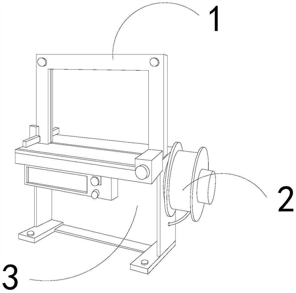
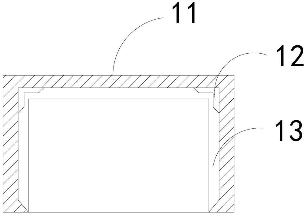
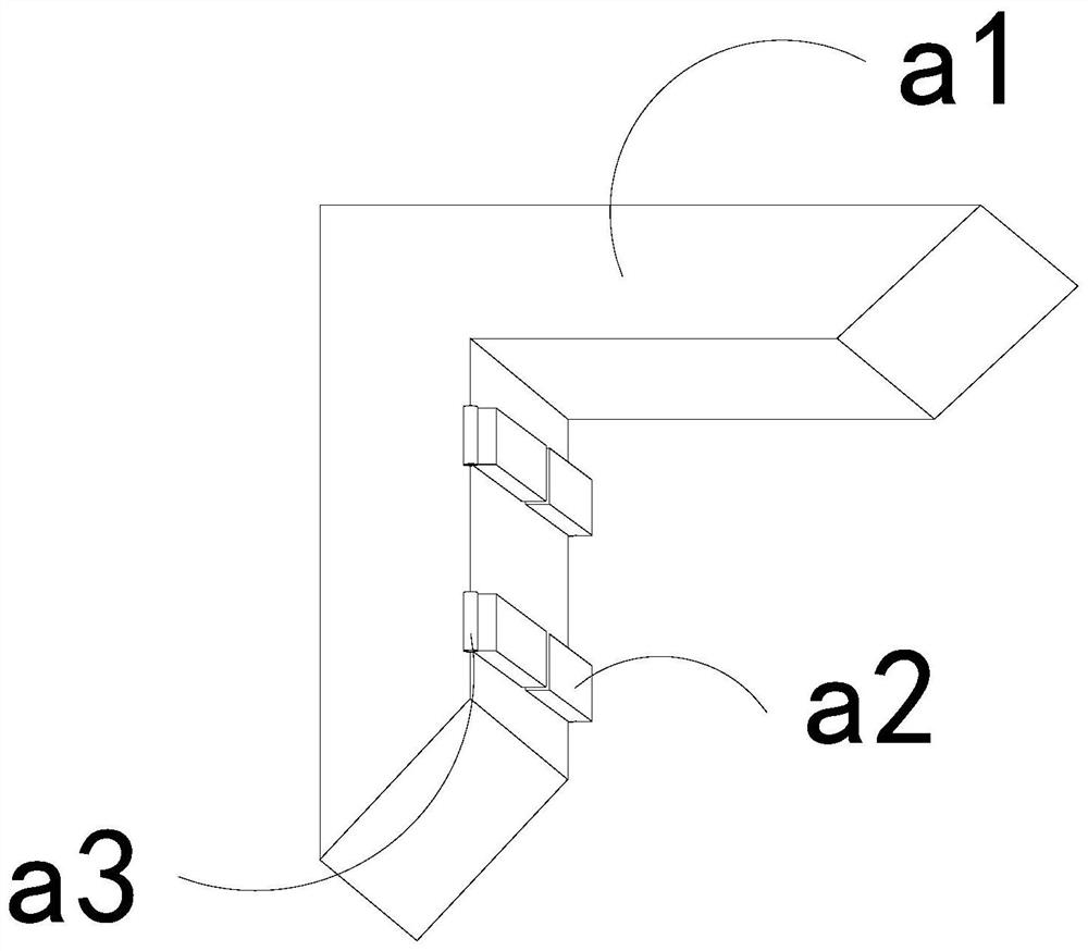
[0026] For example figure 1 -example Figure 5 Shown:

[0027] The present invention provides a differential chain assembly line for bundling and loading and unloading. The folding frame 1 is embedded in the upper end position of the strapping machine 3; the bending frame 1 includes a frame 11, a positioning mechanism 12, and a guide cavity 13, and the positioning mechanism 12 is embedded and connected with the inner side of the frame 11, and the guiding The cavity 13 and the frame 11 are an integral structure.

[0028] Wherein, the positioning mechanism 12 includes a plate body a1, a swing plate a2, and a connecting roller a3. The swing plate a2 is movably engaged with the plate body a1 through the connecting roller a3. There are four swing plates a2, and two One is a group of evenly distributed in parallel on the inner lower end of the plate body a1 , and the packing tape can be clamped by the tape collecting roller 2 .

[0029] Wherein, the connecting roller a3 includes...

Embodiment 2

[0034] For example Figure 6 -example Figure 8 Shown:

[0035] Wherein, the swing plate a2 includes an upper frame c1, a springback piece c2, and a shrinkage frame c3, the springback piece c2 is movably engaged with the upper frame c1, and the shrinkage frame c3 is installed on the springback piece c2 and the upper frame c1 Between the inner walls of the bag, the reverse thrust generated by the packaging belt on the resilient piece c2 can make the resilient piece c2 shrink upward along the upper frame c1, so that the packaging bag can smoothly pass between the surface of the object and the resilient piece c2.

[0036] Wherein, the resilient sheet c2 includes an elastic rod c21, a contact block c22, a bottom plate c23, and a receiving plate c24. connection, the bottom plate c23 and the receiving plate c24 are an integrated structure, and the contact blocks c22 are provided in five, and are evenly distributed in parallel on the bottom plate c23, and the contact block c22 can ...


PUM


Abstract

The invention discloses a differential chain assembly line for bundling, loading and unloading. The differential chain assembly structurally comprises a bending frame, a tape collecting roller and a bundling machine, wherein the tape collecting roller is movably clamped with the edge side of the bundling machine; and the bending frame is fixedly embedded in the upper end of the bundling machine. An upper connecting plate can be tightly attached to the inner side of an outer ring under cooperation of a linkage rod through gravity generated by bending of a packaging tape, and swing plates can fix the packaging tape to be bent and dropped, so that the situation that the packaging tape is prone to being bent downwards and dropped in advance when the packaging tape is drawn to ascend along thebending frame since the packaging tape used for bundling is light and soft is effectively avoided; and the packaging tape enters spaces between the swing plates and connecting rollers to squeeze a spring-back piece, and the spring-back piece can contract upwards, so that the packaging tape can be drawn between the spring-back piece and a plate body more smoothly, and the situation that the packaging tape is hard to draw after being tightly attached to the swing plates due to the fact that the surface of the packaging tape is soft is effectively avoided.

Description

technical field [0001] The invention relates to the field of differential chain assembly lines, in particular to a differential chain assembly line for bundling and loading and unloading. Background technique [0002] The strapping machine for the differential chain assembly line is mainly used for the packaging of the differential chain assembly line. By placing the packing box to be bundled on the operating table of the strapping machine for the differential chain assembly line, the strapping device is used to pull the packing belt along the Sliding against the upper end of the bending frame until the packing tape is wrapped around a circle and then tightened on the packing box, it is a common equipment for bundling and unloading of the differential chain assembly line. Based on the above description, the inventors found that the existing one The differential chain assembly line mainly has the following deficiencies, for example: [0003] Since the strapping machine for t...

Claims


Application Information

Patent Timeline
Patent Type & Authority Applications(China)
IPC IPC(8): B65B13/02B65B13/22B65B41/12
CPCB65B13/02B65B13/22B65B41/12
Inventor 李国辉
Owner 广州玛宝伦贸易有限公司
Learn More