
Textile yarn pay-off device

A pay-off device and textile yarn technology, which is applied in the field of textile yarn pay-off devices, can solve problems such as device fixing troubles, yarn bobbins falling off, and easy jamming, etc., to prevent yarn clamping and breaking, and yarn twitching Smooth, easy installation and removal effect

Inactive Publication Date: 2020-06-12
刘凌
View PDF0 Cites 1 Cited by
  • Summary
  • Abstract
  • Description
  • Claims
  • Application Information

AI Technical Summary

Problems solved by technology

[0003] The purpose of the present invention is to provide a textile yarn pay-off device to solve the problem of using the yarn to rotate on the yarn drum to release the yarn in the background technology, which is easy to get stuck and inconvenient for normal textile operations. Fixed on the bracket, it is easy to block the winding, causing unsafe production phenomena such as yarn bobbin falling off, and the general fixing device is only equipped with a lead wire ring, which makes it inconvenient to fix the direction of the lead wire. At the same time, the fixed yarn bobbin model must be more practical. Poor, and the device is troublesome to fix, making it difficult to disassemble and replace the device

Method used

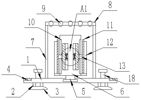
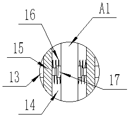
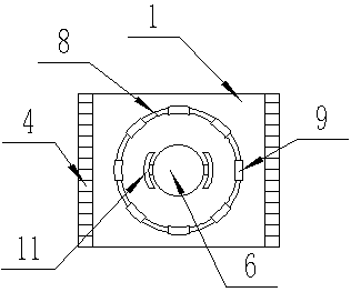

Image

  • Textile yarn pay-off device
  • Textile yarn pay-off device
  • Textile yarn pay-off device

Examples


Embodiment Construction

[0017] The following will clearly and completely describe the technical solutions in the embodiments of the present invention with reference to the accompanying drawings in the embodiments of the present invention. Obviously, the described embodiments are only some, not all, embodiments of the present invention. Based on the embodiments of the present invention, all other embodiments obtained by persons of ordinary skill in the art without making creative efforts belong to the protection scope of the present invention.

[0018] see Figure 1-3 , the present invention provides a technical solution: a textile yarn pay-off device, comprising a base plate 1, the upper sides of the base plate 1 are covered with soft cushions 4, and the lower end of the base plate 1 is vertically fixedly connected with support rods on both sides 2. The inside of the support rod 2 is set to be hollow, and the lower end of the support rod 2 is fixedly connected with a suction cup 3, which facilitates ...


PUM


Abstract

The invention discloses a textile yarn pay-off device. The device comprises a bottom plate, the upper portions of the two sides of the bottom plate are covered with soft cushions, supporting rods arevertically and fixedly connected to the two sides of the lower end of the bottom plate, and screw rods are vertically inserted into the center of the supporting rods in a penetrating mode; supportingframes are vertically and fixedly connected to the upper portion of the bottom plate, and a fixing ring is horizontally arranged above the supporting frames; and a rotating shaft is vertically inserted in the center of the upper end of the bottom plate, a fixing shaft is fixedly connected to the upper end of the rotating shaft, clamping grooves are formed in the two sides of the fixing shaft, andcavities are vertically formed in the two sides inside the fixing shaft. According to the device, pressing plates are retracted into the clamping grooves, meanwhile, movable plates slide towards the inner sides along the cavities, extendable rods are compressed, springs are pressed and deformed, a yarn barrel sleeves the outer side of the fixing shaft, the yarn barrel can be fixed through the spring resetting elastic force when the pressing plates are loosened, the yarn barrels with different diameters can be fixed, and the practicability of the device is improved.

Description

technical field [0001] The invention relates to the field of spinning equipment, in particular to a textile yarn unwinding device. Background technique [0002] In the textile industry, textile yarn reels are often used. The existing pay-off devices are generally fixed and have poor flexibility, and the yarn is rotated on the yarn reel to pay off the yarn, which is easy to get stuck and inconvenient. In normal textile operation, the yarn bobbin is fixed on the bracket, which is easy to block the winding and cause unsafe production phenomena such as yarn bobbin falling off, and the general fixing device is only equipped with a lead ring, which makes it inconvenient to fix the direction of the lead wire. The type of yarn bobbin must have poor practicability, and the trouble of fixing the device makes it difficult to disassemble and replace the device, so a device is urgently needed to solve the above problems. Contents of the invention [0003] The object of the present inv...

Claims


Application Information

Patent Timeline
Patent Type & Authority Applications(China)
IPC IPC(8): B65H49/36B65H57/06
CPCB65H49/36B65H57/06
Inventor 刘凌
Owner 刘凌
Learn More