Turning-over assistor and control method

A control method and technology of an auxiliary machine, applied in the field of medical devices, can solve the problems of single function and inconvenient back care of patients, etc.

Pending Publication Date: 2021-02-23
LIUZHOU CITY HEALTHCARE HOSPITAL FOR WOMEN & CHILDREN
1 Cites 0 Cited by

AI-Extracted Technical Summary

Problems solved by technology

[0003] However, these current tools for assisting patients in turning over have a single function, and can only turn the patient's body at a certain angle, and the angle is often less than 45°, which can reduce the occurrence of pressure sores in patients to a certain extent. In the process of assisting the patient to turn...

Method used

1, for some severe or paralyzed patients whose hands can still move and are clear-headed, the setting of remote controller 10 can give them the space to choose their posture state independently, reduce their sense of restraint, increase their comfort, improve Their joy of life can reduce the world-weariness of such patients due to long-term bed rest and inability to move independently.
1, for the patient who cannot turn the body voluntarily, the present embodiment can automatically complete the timing turning over to the patient through the control of the controller 9 to the first power unit 2, the second power unit 5 and the third power unit 7 Operation, help such patients change the pressure of each support point of the body, improve the blood circulation on the back of such patients, effectively reduce the possibility of pressure sores in such patients, and greatly reduce the need for nursing staff to manually help such patients change their lying positions Labor intensity saves working time; in this embodiment, the program to help patients turn over automatically can be personalized through the control panel 8, effectively...

Abstract

The invention relates to the field of medical instruments, in particular to a turning-over assistor and a control method. The turning-over assistor comprises a base, a first power unit, a connecting block, a bed body, a second power unit, a plurality of protective plates, a plurality of third power units, a control panel, a controller and a remote controller; the base is fixedly arranged on the ground; the first power unit is fixedly arranged on the base; the first power unit is connected with the bed body through the connecting block; the second power unit is arranged on the bed body; the protective plates are arranged on the bed body; the third power units are arranged on the protective plates; and each protective plate is further provided with an air bag and an air pump. According to the turning-over assistor, through control of the controller on the first power unit, the second power unit, the plurality of third power units and the plurality of air pumps, a patient can be automatically turned over at regular time, so that pressure sores of the patient are effectively reduced, the labor intensity of a nurse to helping the patient change a prone position manually at regular timeis relieved, and the working time is saved; and the front part of the body of the patient can be cushioned on the protective plates, and the back is exposed, so that nursing or treatment is facilitated.

Application Domain

Nursing bedsAmbulance service

Technology Topic

PATIENT PHYSICALPressure sore +9

Image

  • Turning-over assistor and control method
  • Turning-over assistor and control method
  • Turning-over assistor and control method

Examples

  • Experimental program(1)

Example Embodiment

[0063]The technical solutions in the embodiments of the present invention will be clearly and completely described below in conjunction with the accompanying drawings in the embodiments of the present invention. Obviously, the described embodiments are only a part of the embodiments of the present invention, rather than all the embodiments. The attached drawings are only used for illustrative purposes, they are only schematic diagrams, not physical drawings, and cannot be understood as a limitation of the patent. In order to better illustrate the specific embodiments of the present invention, some parts of the drawings may be omitted or enlarged. Or reduction does not represent the size of the actual product. For those skilled in the art, it is understandable that certain well-known structures, components and descriptions in the drawings may be omitted. Based on the embodiments of the present invention, those of ordinary skill in the art All other embodiments obtained without creative work fall within the protection scope of the present invention.
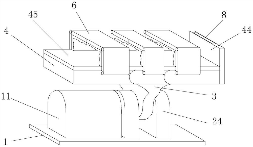
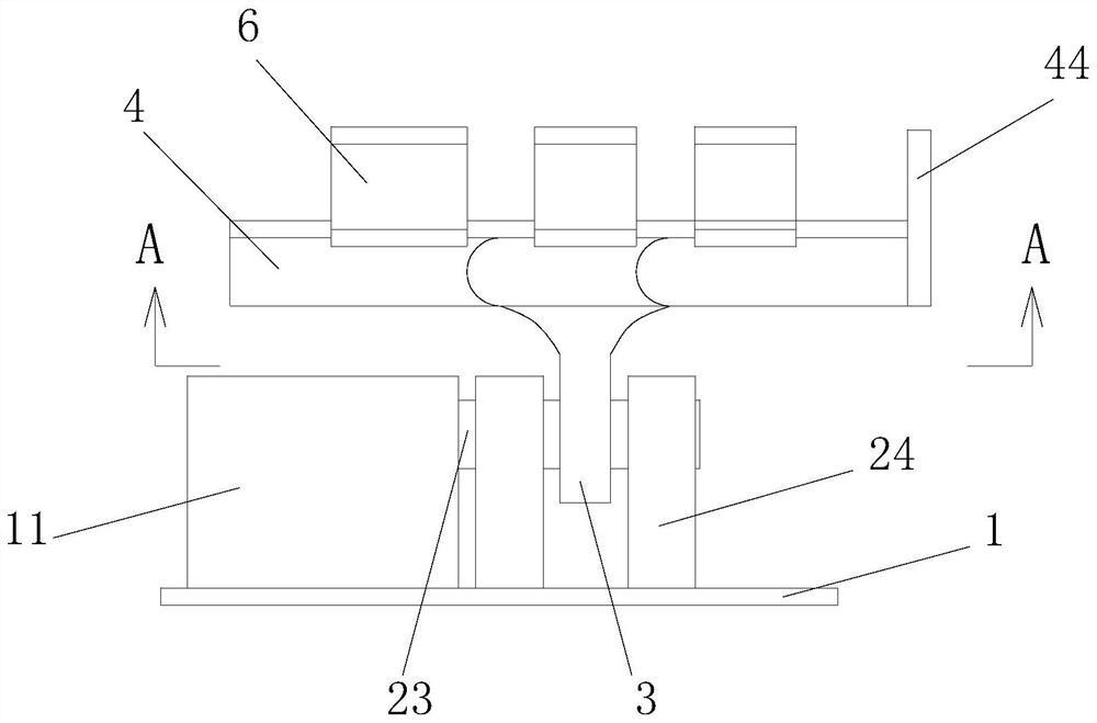
[0064]SeeFigure 1 to Figure 10 In a preferred embodiment of the present invention, a turn-over auxiliary machine and control method include a base 1, a first power unit 2, a connecting block 3, a bed body 4, a second power unit 5, and several guard plates 6 , A number of third power units 7, a control panel 8 and a controller 9. The controller in this embodiment is a programmable logic controller (PLC);
[0065]The base 1 is fixed on the ground. In order to enable the base 1 to withstand a large moment without turning over during use in this embodiment, the base 1 is preferably fixedly connected to the ground through a number of expansion screws; the first power unit 2 Fixed at the upper end of the base 1, the rotation axis of the output shaft 23 of the first power unit 2 is arranged horizontally, and the output shaft 23 of the first power unit 2 is connected to the fixed connection block 3; the length direction of the bed 4 is parallel to the first power unit 2 is the rotation axis of the output shaft 23, the bottom of the bed body 4 is fixedly connected with the connecting block 3. The bed body 4 is located above the base 1 through the connecting block, and with the connecting block 3 relative to the base 1 under the action of the first power unit 2. Rotation; In this embodiment, the connecting block 3 is fixedly connected to the bottom of the middle plate 42; the first power unit 2 includes a motor 21, a gear set 22 for deceleration and distance increase, an output shaft 23 and two support frames 24, a motor 21 Fixed on the bottom plate, the motor 21 is connected to the controller 9, the motor 21 is connected to the output shaft 23 through the gear set 22, the two support frames 24 are arranged at intervals, the two support frames 24 are respectively provided with bearings, the output shaft 23 is arranged horizontally, and the output shaft 23 is rotatably connected with the support frame 24 through a bearing, the rotation axis of the rotation connection is arranged horizontally, and the connecting block 3 is connected to the output shaft 23 at a position between the two support frames 24; preferably, the gear set 22 includes a worm gear set, so that When it is necessary to keep the bed 4 at a certain angle, disconnect the power connection of the motor 21. The reverse self-locking feature of the worm gear set can prevent the bed 4 from rotating on its own; preferably, it also includes a chassis 11 and a chassis 11 is installed on the base 1, the controller 9, the motor 21 and the gear set 22 are all arranged in the chassis 11.
[0066]The bed body 4 includes a lower plate 41, a middle plate 42 and an upper plate 43. The lower plate 41, the middle plate 42 and the upper plate 43 are arranged in sequence along the length of the bed body 4. The lower plate 41 and the middle plate 42 are rotationally connected, and the rotational connection The rotation axis is perpendicular to the length direction of the bed body 4, the upper plate 43 and the middle plate 42 are rotationally connected, and the rotation axis of the rotation connection is perpendicular to the length direction of the bed body 4; the second power unit 5 is arranged on the bed body 4, and the second power The unit 5 is connected to the lower plate 41, the middle plate 42 and the upper plate 43, and the second power unit 5 controls the rotation of the lower plate 41 relative to the middle plate 42 and the rotation of the upper plate 43 relative to the middle plate 42;
[0067]There are two guard plates 6 in a group, and the two guard plates 6 of the same group are arranged facing each other. At least one set of guard plates 6 are respectively provided on the lower plate 41, the middle plate 42 and the upper plate 43, and the two guard plates 6 of the same group are respectively connected On both sides in the width direction of the board where it is located, the guard 6 mounted on the lower board 41 is located at the end of the lower board 41 facing the middle board 42, so that the patient's feet are not blocked by the guard 6, and the guards 6 mounted on the upper board 43 The guard plate 6 is located at one end of the upper plate 43 facing the middle plate 42 so that the patient’s head is not covered by the guard plate 6; the guard plate 6 includes a first baffle 61, a second baffle 62, an airbag 63 and an air pump 64. One end in the length direction of a baffle 61 is rotatably connected to the bed body 4, the rotation axis of the rotation connection is parallel to the length direction of the corresponding plate surface of the bed body 4 where the guard plate 6 is located, and the rotation axis is parallel to the corresponding first stop In the width direction of the plate 61, the other end in the length direction of the first baffle 61 is connected with one end in the length direction of the second baffle 62, and the rotation axis of the rotation connection is parallel to the bed 4 where the guard plate 6 is located. Corresponding to the length direction of the plate surface, the rotation axis is parallel to the width direction of the second baffle 62, and the other end in the length direction of the second baffle 62 is a free end; the airbag 63 is provided on the plate surface of the first baffle 61 And on the surface of the second baffle 62, the first baffle 61 is set on the airbag 63 to be the first baffle 61 upright, and the first baffle 61 faces the side where the other guard 6 of the same group is located. , The second baffle 62 is set on the airbag 63 surface when the second baffle 62 is vertically upward, and the second baffle 62 faces the surface of the side where the other protective plate 6 of the same group is located, and the air pump 64 is arranged in the protective plate 6. , The air pump 64 is connected to the airbag 63, and the air pump 64 controls the expansion and collapse of the airbag 63; a third power unit 7 is provided in each guard plate 6, and the third power unit 7 is connected between the first baffle 61 and the bed board 4 The rotating connecting shaft, the rotating connecting shaft between the first baffle 61 and the second baffle 62, the third power unit 7 controls the rotation of the first baffle 61 relative to the bed plate and the second baffle 62 relative to the first baffle 61 Turn; seefigure 1 In this embodiment, the two guard plates 6 in the same group are perpendicular to the surface of the bed 4 where their first baffles 61 are located, and their second baffles 62 are parallel to the bed where they are located. 4 and the free ends of the two second baffles 62 are facing each other, the free ends of the two second baffles 62 abut against each other.
[0068]The composition of the second power unit 5 and its connection relationship with the bed 4, the composition of the third power unit 7 and its connection relationship with the guard plate 6 in this embodiment are in the prior art, and are commonly found in various mechanical arms , I won’t repeat it here.
[0069]The control panel 8 is arranged on the bed body 4. In this embodiment, the bed body 4 further includes a tail plate 44. The surface of the tail plate 44 is perpendicular to the surface of the lower plate 41, and the tail plate 44 is fixed in the back of the lower plate 41. At one end of the board 42, the control panel 8 is arranged on the tail plate 44, the control panel 8 is preferably a touch screen, the control panel 8, the first power unit 2, the second power unit 5, the third power unit 7, and several air pumps 64 Connect to the controller 9 respectively.
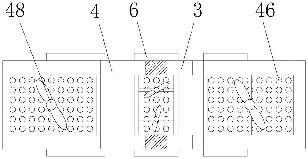
[0070]Seeimage 3 Preferably, it also includes a soft pad 45, a number of fans 48 and a number of temperature sensors 47. The soft pad 45 covers the upper surface of the bed body 4. The lower plate 41, the middle plate 42 and the upper plate 43 are all perpendicular to the respective plate surfaces. A number of through holes 46 are respectively opened in the direction. The lower plate 41 is installed on the side facing away from the soft pad 45, the middle plate 42 on the side facing away from the soft pad 45, and the upper plate 43 on the side facing away from the soft pad 45. There is at least one fan 48, and the blowing direction of each fan 48 is perpendicular to the corresponding board surface of the bed body 4. The fan 48 is connected with the controller 9, between the lower board 41 and the cushion 45, the middle board 42 and the soft A number of temperature sensors 47 are respectively arranged between the pads 45 and between the upper plate 43 and the soft pad 45, and all the temperature sensors 47 are connected to the controller 9.
[0071]Based on the above content, the control mode of this embodiment includes automatic mode and manual mode, wherein the control process and method of the automatic mode are:
[0072]Program input:
[0073]1. Select the reset option of control panel 8;
[0074]2. On the control panel 8, select the air pressure value of the airbag 63 corresponding to the lower plate 41, the middle plate 42 and the upper plate 43, enter the rollover angle, and enter the corresponding fan 48 on the lower plate 41, the middle plate 42 and the upper plate 43 to start Stop temperature threshold; calibrate the built-in time of the controller 9 through the control panel 8 to the local standard time, and enter the number of days and single turn over information into the controller 9 through the control panel 8. The single turn over information includes: turn over start time, Turning over time and direction;
[0075]3. Select the startup option of Control Panel 8.
[0076]Within a range of execution days, only one program input is required. Within a range of execution days, if a program is input multiple times, the program inputted later will overwrite the program inputted previously.
[0077]Program execution:
[0078]1. Reset: After the reset option of the control panel 8 is selected, the controller 9 starts the first power unit 2, the second power unit 5, and all the third power units 7 to make the lower board 41, the middle board 42 and the upper board 43 The board surfaces of are placed horizontally, so that all the first baffles 61 and all the second baffles 62 are vertically downward;
[0079]2. Please refer toFigure 6 withFigure 7 , Turn over: When the built-in time of the controller 9 is consistent with the turn over start time of a certain single turn over information, the controller 9 activates all the third power units 7 so that all the first baffles 61 are turned upright So that all the second baffle plates 62 in the same group are placed horizontally and the two free ends are facing each other. The controller 9 activates all the air pumps 64 to inflate the corresponding airbags 63 to make the airbags 63 The air pressure is equal to the pre-selected air pressure. The controller 9 activates the first power unit 2 according to the turning direction of the single turn information to tilt the bed 4 in the preset direction, and the tilt angle is equal to the input turning angle; The built-in time is consistent with the turn-over end time of the single turn-over information. The controller 9 activates the first power unit 2 to make the bed 4 horizontally straight, the controller 9 activates the air pump 64, and exhausts the gas in the air bag 63, and the controller 9 activates the first power unit 2. The three-power unit 7, so that all the first baffles 61 and all the second baffles 62 are placed vertically downward;
[0080]3. The start and stop of the fan 48: When the temperature detected by the corresponding temperature sensors 47 on the lower board 41, the middle board 42 and the upper board 43 is greater than the corresponding set temperature threshold, the controller 9 controls the fan 48 of the corresponding part to turn on, and the current board 41. The temperature detected by the corresponding temperature sensors 47 on the middle board 42 and the upper board 43 is less than the correspondingly set temperature threshold, and the controller 9 controls the fan 48 in the corresponding part to stop.
[0081]The air pressure values ​​of the corresponding airbags 63 on the lower plate 41, the middle plate 42 and the upper plate 43 selected on the control panel 8 are correspondingly applied to the manual mode.
[0082]The control process and method of manual mode are:
[0083]1. Pause automatic mode: select the pause option of control panel 8;
[0084]2. Select the sitting position option, left turn option, right turn option, left turn care option, right turn care option, lying down option, upper fan option, middle fan option, and lower fan option on the control panel 8 as needed;
[0085]SeeFigure 5 , Select the sitting position option: the controller 9 controls the first power unit 2 and the second power unit 5, so that the lower board 41, the middle board 42 and the upper board 43 are placed horizontally, and the controller 9 controls the third power unit 7 , So that all the first baffles 61 on the lower plate 41 are perpendicular to the plate surface of the lower plate 41 facing up, so that the plate surfaces of all the second baffle plates 62 in the same group on the lower plate 41 are placed horizontally and the two free ends are directly opposite, All the first baffles 61 and all the second baffles 62 on the middle plate 42 are placed vertically downwards, so that all the first baffles 61 on the upper plate 43 are perpendicular to the surface of the upper plate 43 facing upward, All the second baffle plates 62 in the same group on the upper plate 43 are placed horizontally and the two free ends are facing, so that all the air pumps 64 on the lower plate 41 and the upper plate 43 are filled with gas into the corresponding airbag 63, Make the air pressure in the corresponding airbag 63 equal to the preselected air pressure; the controller 9 controls the second power unit 5 to rotate the lower plate 41 downwards relative to the middle plate 42 by a certain angle, which is less than or equal to 90°, while making the upper plate 43 relatively center The plate 42 rotates upward by a certain angle, which is less than or equal to 90°.
[0086]Select the left turn option: the controller 9 controls the first power unit 2 and the second power unit 5 so that the lower board 41, the middle board 42 and the upper board 43 are placed horizontally, and the controller 9 starts all the third power units 7. Turn all the first baffle plates 61 to the upright position, so that all the second baffle plates 62 in the same group are placed horizontally with the two free ends facing each other, and the controller 9 starts all the air pumps 64 Fill the corresponding airbag 63 with air so that the air pressure in each airbag 63 is equal to the preselected air pressure. The controller 9 activates the first power unit 2 to rotate the bed 4 to the left side of the corresponding patient's prone position. The tilt angle is 110 ° -120°;
[0087]Select the right turn option: the controller 9 controls the first power unit 2 and the second power unit 5, so that the lower plate 41, the middle plate 42 and the upper plate 43 are placed horizontally, and the controller 9 starts all the third power units 7. Turn all the first baffle plates 61 to the upright position, so that all the second baffle plates 62 in the same group are placed horizontally with the two free ends facing each other, and the controller 9 starts all the air pumps 64 Fill the corresponding airbag 63 with air so that the air pressure in each airbag 63 is equal to the preselected air pressure. The controller 9 activates the first power unit 2 to rotate the bed 4 to the right side of the corresponding patient's prone position. The rotation angle is 110° Between -120°;
[0088]Select the right turn care option: seeFigure 6 , The controller 9 controls the first power unit 2 and the second power unit 5 so that the surfaces of the lower board 41, the middle board 42 and the upper board 43 are all placed horizontally, and the controller 9 activates all the third power units 7 so that all All the first baffle 61 of the same group is turned to the vertical upward position, so that the surface of all the second baffles 62 in the same group are placed horizontally and the two free ends are facing each other. The controller 9 activates all the air pumps 64 to the corresponding airbags Fill 63 with air so that the air pressure in each airbag 63 is equal to the preselected air pressure, please refer toFigure 8 , The controller 9 activates the first power unit 2 to make the bed 4 rotate to the right side of the corresponding patient's prone position, the rotation angle is between 110°-120°, and the controller 9 controls all the left side of the corresponding patient's prone position The air pump 64 evacuates the air in all airbags 63 on this side, and the controller 9 controls all the first baffle 61 and the second baffle 62 on this side to rotate to the left side of the patient's prone position, so that all the first baffles on this side The baffle 61 and the second baffle 62 are both perpendicular to the upper surface of the bed 4 and face the back of the bed 4; the controller 9 controls the first power unit 2 and the second power unit 5 to make the bed 4 face the corresponding patient lying position Turn the left side of the bed until the upper surface of the bed 4 is level. While the bed 4 is turning, all the first baffles 61 located on the right side of the corresponding patient's prone position rotate to the right of the corresponding patient's prone position, and the rotational angular velocity The size of is synchronized with the size of the rotation angular velocity of the bed body 4.
[0089]Select the left-turn care option: seeFigure 6 , The controller 9 controls the first power unit 2 and the second power unit 5 so that the surfaces of the lower board 41, the middle board 42 and the upper board 43 are all placed horizontally, and the controller 9 activates all the third power units 7 to make all All the first baffle 61 of the same group is turned to the vertical upward position, so that the surface of all the second baffles 62 in the same group are placed horizontally and the two free ends are facing each other. The controller 9 activates all the air pumps 64 to the corresponding airbags Fill 63 with air so that the air pressure in each airbag 63 is equal to the preselected air pressure. The controller 9 activates the first power unit 2 to rotate the bed 4 to the left side of the corresponding patient's lying position. The rotation angle is between 110°-120° In between, the controller 9 controls all the air pumps 64 located on the right side of the corresponding patient's prone position to exhaust the air in all the airbags 63 on that side, and the controller 9 controls all the first baffle 61 and the second baffle 62 on this side to correspond to each other. The right side of the patient's prone position is rotated so that all the first baffle 61 and the second baffle 62 on this side are perpendicular to the upper surface of the bed 4 and face the back of the bed 4; the controller 9 controls the first power unit 2 With the second power unit 5, the bed 4 rotates to the right side of the corresponding patient's prone position until the upper surface of the bed 4 is level. While the bed 4 rotates, all the first ones located on the left side of the corresponding patient's prone position The baffle 61 rotates to the left side of the lying position corresponding to the patient, and the rotation angular velocity is synchronized with the rotation angular velocity of the bed 4.
[0090]SeeFigure 4 , Select the lie down option: the controller 9 starts the first power unit 2, the second power unit 5, and all the third power units 7, and executes the actions of the previous option in reverse order and reverse to make the lower board 41 and the middle board 42 The surface of the upper plate 43 and the upper plate 43 are placed horizontally, so that all the first baffles 61 and all the second baffles 62 are placed vertically downward.
[0091]The upper fan 48 option is selected for a single number of times: the controller 9 starts the fan 48 at the bottom of the upper board 43, and the upper fan 48 option is selected for an even number of times: the controller 9 turns off the fan 48 at the bottom of the upper board 43.
[0092]The middle fan 48 option is selected for a single number of times: the controller 9 starts the fan 48 at the bottom of the middle board 42, and the middle fan 48 option is selected for an even number of times: the controller 9 turns off the fan 48 at the bottom of the middle board 42.
[0093]Select the lower fan 48 option for a single number of times: the controller 9 starts the fan 48 at the bottom of the lower board 41, and select the lower fan 48 option for an even number of times: the controller 9 turns off the fan 48 at the bottom of the lower board 41.
[0094]Need to continue to execute automatic mode in manual mode, select the start option on the control panel 8.
[0095]Based on the above content, the usage method of this embodiment is:
[0096]In the manual mode, select the option of lying flat to make the patient lie flat on the upper surface of the bed 4; if you need to automatically turn the patient at regular intervals, to reduce the occurrence of pressure sores and improve the patient's lying comfort, execute through the control panel 8. Automatic mode; if you need to help the patient with spitting or vomiting, select the left turn option or the right turn option in manual mode according to the actual situation; if you need to put the patient in a sitting position to feed or watch TV to relieve boredom, in manual mode Select the sitting position option; if you need to care or treat the back of the patient, select the left-turn care option or the right-turn care option in the manual mode according to the actual situation, so that the patient is supported by the corresponding side shield 6, with the back tilted toward Up; if you need to restore the patient to lying flat, select the option of lying flat; if you need to cool the patient in manual mode, select individual or all of the upper fan 48 option, middle fan 48 option, and lower fan 48 option.
[0097]In this embodiment, in order to enable the bed to be turned smoothly and the height of the bed is suitable for nursing and treatment operations, considering that this embodiment is used for severely ill or paralyzed patients whose bodies cannot move autonomously, the width of the upper surface of the bed It is appropriate to be less than 90CM. When the upper surface of the bed is placed horizontally, its height should be lower than 100cm.
[0098]Based on the above content, the beneficial effects of this embodiment are:
[0099]1. For patients who cannot turn their bodies on their own, in this embodiment, the controller 9 controls the first power unit 2, the second power unit 5 and the third power unit 7, which can automatically complete the timing turning operation for the patient, which helps Such patients change the pressure of each support point of the body, improve the blood circulation on the back of such patients, effectively reduce the possibility of pressure sores in such patients, and greatly reduce the labor intensity of nursing staff to help such patients change their prone position regularly. Save working time; the program of this embodiment to help the patient turn over automatically can be personalized through the control panel 8, which can effectively meet the needs of patients in different situations and has a wide range of applications.
[0100]2. For patients who are conscious but unable to sit and lie on their own, the controller 9 controls the second power unit 5 and the third power unit 7 in this embodiment to help the patient complete the replacement of the sitting and lying positions. When the patient needs to eat or watch TV to relieve boredom, select the sitting position option. In this embodiment, the lower board 41 is rotated downwards relative to the middle board 42 by a certain angle, while the upper board 43 is rotated upwards relative to the middle board 42 by a certain angle, so that the patient can easily complete The transition from prone position to sitting position.
[0101]3. When a patient who is inconvenient to move on his own needs spitting or vomiting, select the left turn option or the right turn option. In this embodiment, the controller 9 controls the first power unit 2 and the third power unit 7 to make the patient With the body tilted down, the patient can easily spit or vomit, and in this embodiment, the first power unit 2 makes the bed 4 as a whole to complete the tilt and turn operation of the patient. At this time, the distance between the patient's head and the ground Closer, and the head is located on the side of the bed 4, whether it is spitting or vomiting, the discharge can be easily spit into the container, and it will not be spit on the bed 4, which greatly reduces spitting or vomiting. It happens that vomited discharge splashes out of the container and pollutes the surrounding environment.
[0102]4. When it is necessary to care or treat the back of the patient, select the left-turn care option or the right-turn care option. In this embodiment, the controller 9 controls the first power unit 2, the second power unit 5, and the third power unit 7. The control enables the front part of the patient's body to be placed on the protective plate 6 and the back is exposed, which greatly facilitates the care or treatment.
[0103]5. In this embodiment, while turning the patient over or sitting up, the guard 6 and the airbag 63 cooperate to keep the patient's posture stable and prevent the patient from slipping or falling off the bed 4; the airbag 63 in this embodiment is adjustable in air pressure The airbag 63 can fit the human body well and has a large contact area with the human body. The airbag 63 supports the patient's body without causing too much pressure on the body, and the patient's comfort is high.
[0104]6. The lower plate 41, the middle plate 42 and the upper plate 43 of this embodiment are all provided with through holes 46, so that the bed body 4 of this embodiment has excellent air permeability. The arrangement of several temperature sensors 47 and several fans 48 further improves The breathability of this embodiment helps the patient reduce the stuffiness of the back and increase the comfort of the patient.
[0105]SeeFigure 1 to Figure 11On the basis of the above embodiment, in the second embodiment, it further includes a remote control 10, the controller 9 is integrated with a wireless module, the remote control 10 is connected to the controller 9 through the wireless module, and the remote control 10 includes a turn button 101 , Sitting position key 102, lying key 103, upper fan key 104, middle fan key 105, and lower fan key 106. In this embodiment, the turn-over key 101 is a self-resetting dual-control switch. This type of switch is common Used on the remote control car handle 108, it can be easily operated in two directions with one finger. Turn on the turn key 101 in one direction. The first power unit 2 rotates the bed 4 in one direction until the turn key 101 is released or The bed 4 reaches the maximum rotation stroke, the first power unit 2 stops the bed 4 and turns on the turn key 101 in the other direction, and the first power unit 2 turns the bed 4 in the other direction until the turn key 101 is released. Or the bed body 4 reaches the maximum rotation stroke, and the first power unit 2 stops the bed body 4 from rotating. Preferably, the maximum rotation stroke of the bed body 4 is a horizontal rotation of 120° from the upper surface of the bed body 4. 103. The sitting position key 102, the upper fan key 104, the middle fan key 105, and the lower fan key 106 are all jog switch keys, which correspond to the lie down option, the sitting position option, the upper fan option, the middle fan option, The function of the lower fan option.
[0106]Preferably, the upper surface of the soft pad 45 is a fluffy surface; the remote control 10 includes a placing board 107 and a handle 108. One of the placing board 107 is provided with a number of magic hooks, and this side is compatible with the upper surface of the soft pad 45. To disassemble and cooperate, a handle 108 is fixed on the other surface of the placing board 107. The handle 108 is a rectangular parallelepiped. The length of the handle 108 is perpendicular to the surface of the board 107. The handle 108 is provided with a turning key 101, a sitting position key 102, and a flat The reclining key 103, the upper fan key 104, the middle fan key 105, and the lower fan key 106; further preferably, one of the handles 108 is provided with a turning key 101 on the side perpendicular to the placement plate 107, and the other on the handle 108 is perpendicular to the side The sitting position key 102, the upper fan key 104, the middle fan key 105, and the lower fan key 106 are set from the top to the next on one side. The top of the handle 108 is provided with the lying key 103.
[0107]Preferably, the controller 9 is connected to a mobile terminal, such as a mobile phone, through a wireless module.
[0108]The beneficial effects of this embodiment are:
[0109]1. For some severely ill or paralyzed patients who can move their hands and are clear-headed, the setting of the remote control 10 can give them space to choose their postures, reduce their sense of restraint, increase their comfort, and improve their lives. Fun, reduce the sense of world weariness caused by such patients due to long-term bed rest.
[0110]2. When the patient needs spitting or vomiting, he can operate the remote control 10 by himself in time to complete turning over for spitting or vomiting, which reduces the patient's spraying of sputum or vomit onto the bed due to untimely detection by the nursing staff 4 On or on the ground.
[0111]3. The patient can select the start and stop of the fan 48 through the remote control 10 according to their own conditions, which greatly improves the comfort of the patient and reduces the occurrence of overheating or overcooling.
[0112]4. The remote control 10 can be detachably matched with the soft cushion 45 through the placement plate 107, so that the remote control 10 can be placed on the surface of the bed 4 more stably, reducing the occurrence of the remote control 10 falling off the bed 4 and leaving the patient control .
[0113]5. The shape of the handle 108 of the remote control 10 of this embodiment is suitable for human hands to hold, and the arrangement of the control keys 101 is very suitable for the operation of the fingers. Even if the patient’s hand has poor mobility, it can be Use this remote control 10.
[0114] 6. The controller 9 is connected to the mobile terminal through the wireless module, so that the nursing staff can remotely understand and operate the patient's posture state through the mobile phone, and further reduce the working pressure of the nursing staff.
[0115] The above description is a detailed description of the preferred and feasible embodiments of the present invention, but the embodiments are not intended to limit the scope of the patent application of the present invention. All equivalent changes or modifications made under the technical spirit of the present invention should belong to The scope of patents covered by the present invention.

PUM

no PUM

Description & Claims & Application Information

We can also present the details of the Description, Claims and Application information to help users get a comprehensive understanding of the technical details of the patent, such as background art, summary of invention, brief description of drawings, description of embodiments, and other original content. On the other hand, users can also determine the specific scope of protection of the technology through the list of claims; as well as understand the changes in the life cycle of the technology with the presentation of the patent timeline. Login to view more.
Why Eureka
Try Eureka