Assembly type steel structure reinforcing support

A technology for reinforcing supports and steel structures, which is applied in building structures, buildings, etc., can solve the problems of time-consuming and labor-intensive installation and disassembly of steel structure supports, support height, fixed support position, and low efficiency of steel structure supports, etc. The effect of installation efficiency, ensuring stability and improving installation efficiency

Active Publication Date: 2021-02-23
THE THIRD CONSTR & ENG OF CCFED +1
View PDF7 Cites 2 Cited by
  • Summary
  • Abstract
  • Description
  • Claims
  • Application Information

AI Technical Summary

Problems solved by technology

[0002] The steel structure bracket is a very commonly used supporting and stable structure in the field of construction. Since the steel structure bracket needs to support the rest of the structure, the volume and weight of the steel structure bracket itself are relatively large. At the same time, most of the existing steel structure brackets are welded or screwed. This will result in time-consuming and labor-intensive installation and disassembly of the steel structure bracket, and the inefficiency of assembling the steel structure bracket
At the same time, the support height and support position of the existing steel structure support are fixed, and it is difficult to adjust according to actual use needs

Method used


Image

  • Assembly type steel structure reinforcing support
  • Assembly type steel structure reinforcing support
  • Assembly type steel structure reinforcing support

Examples


Embodiment 1

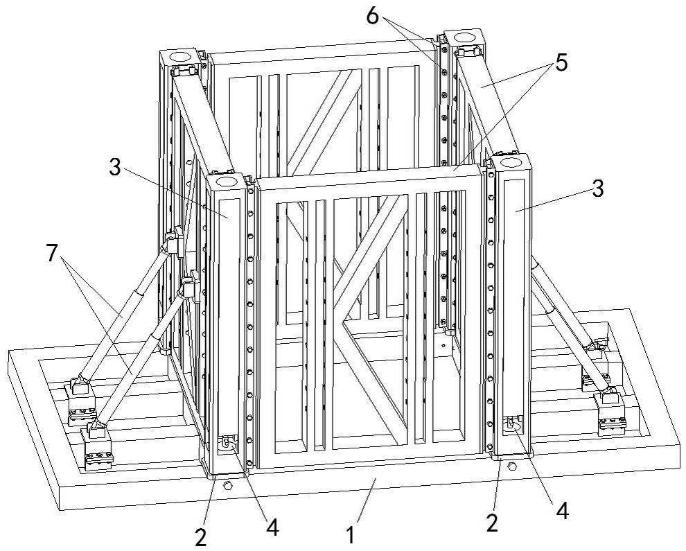
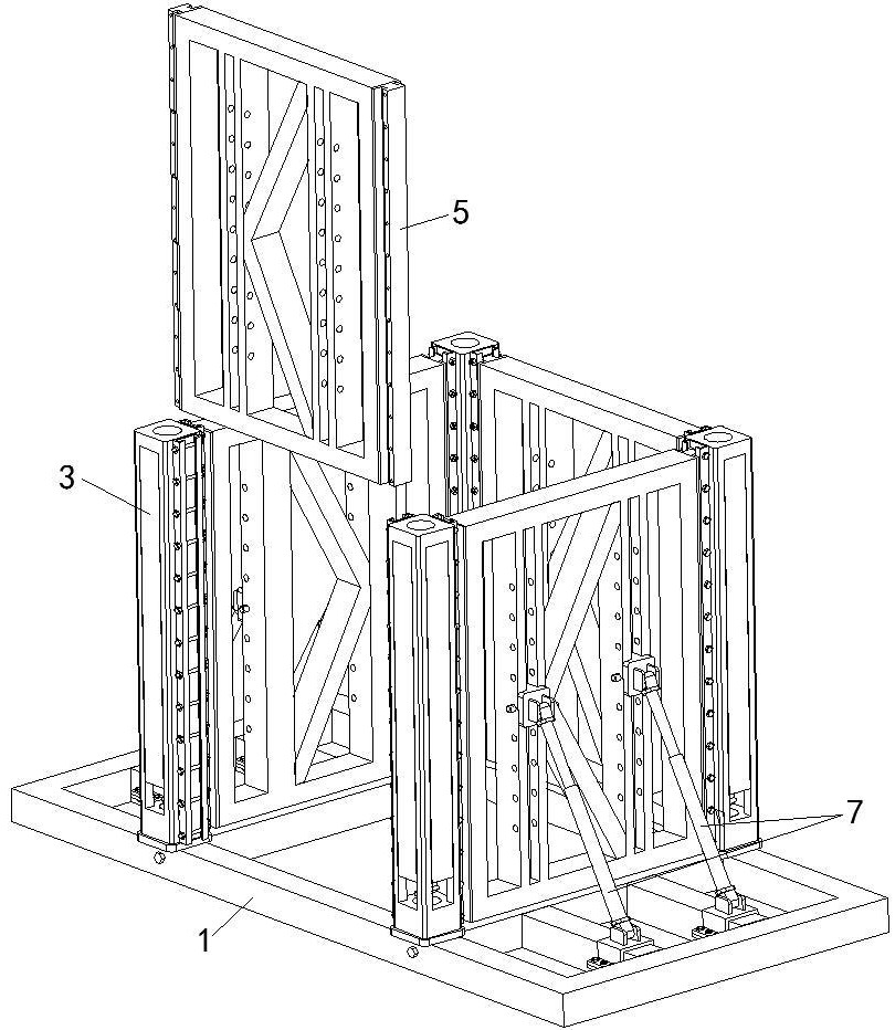
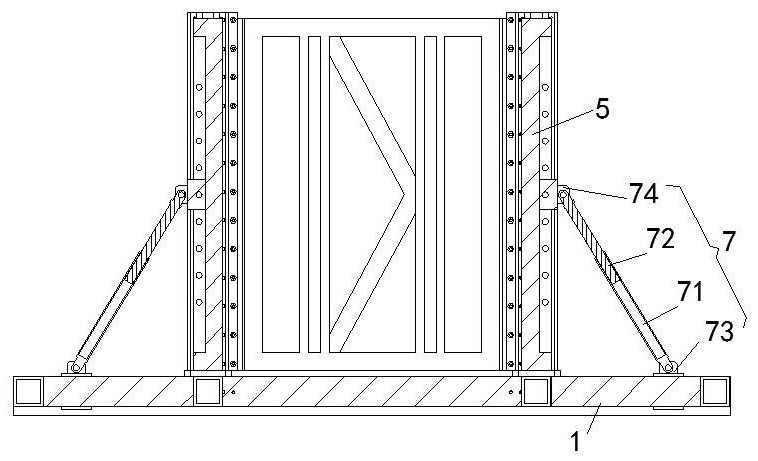
[0027] A kind of assembled steel structure reinforcement bracket of this embodiment, such as Figure 1-Figure 5 As shown, it includes a rectangular reinforced base 1, the four corners of the top rectangular area of ​​the reinforced base 1 are clamped with a transfer support 2, and the top of the transfer support 2 is clamped with a reinforcement column 3. A column tensioning assembly 4 is arranged between the top of the support 2 and the bottom of the reinforcement column 3; the side of the reinforcement column 3 is provided with an assembly groove along the vertical direction, and the assembly on the two adjacent reinforcement columns 3 The support assembly 5 is mounted on sliding cards between the grooves, and the side wall of the assembly groove is provided with a locking device 6 for locking the position of the support assembly 5; An oblique support assembly 7 , one end of the telescopic oblique support assembly 7 is slidingly hinged to the top of the reinforced base 1 , a...

Embodiment 2

[0033] This embodiment is further optimized on the basis of embodiment 1, such as Figure 4 and Figure 5 As shown, the top of the transfer support 2 is provided with a transfer cone 21 with upper, lower pins, and the top of the transfer cone 21 is provided with a threaded hole for installing the column tensioning assembly 4. The reinforcement The bottom of the upright column 3 is provided with a conical socket which is plugged and joined with the adapter cone 21 .

[0034] Through the cooperation and splicing between the tapered socket at the bottom of the reinforcement column 3 and the transfer cone 21 provided on the top of the transfer support 2, the installation of the reinforcement column 3 on the top of the transfer support 2 is guided, and at the same time, the reinforcement column 3 installs more smoothly. After the bottom end surface of the reinforcement column 3 is in contact with the top end surface of the transfer support 2, it indicates that the reinforcement c...

Embodiment 3

[0037] This embodiment is further optimized on the basis of above-mentioned embodiment 1 or 2, such as Figure 4 and Figure 5As shown, the column tensioning assembly 4 is a locking cone 41 with a large top and a small bottom, and the bottom of the locking cone 41 is threadedly connected with the threaded hole of the adapter cone 21 through a connecting stud; There is a conical pressing port coaxial with the conical socket coaxially arranged with the locking cone 41 inside, and the bottom of the conical compressing port is connected with the top of the tapered socket.

[0038] Firstly, the reinforcement column 3 is installed on the top of the transfer support 2, so that the tapered socket at the bottom of the reinforcement column 3 is spliced ​​with the transfer cone 21 at the top of the transfer support 2 to realize the pre-positioning installation of the reinforcement column 3. Then the connecting stud at the bottom of the locking cone 41 can be screwed into the threaded ho...


PUM


Abstract

The invention discloses an assembly type steel structure reinforcing support. The assembly type steel structure reinforcing support comprises a rectangular reinforcing base, adapter supports are clamped at the four corners of a rectangular area of the top of the reinforcing base, reinforcing stand columns are clamped at the tops of the adapter supports, and stand column tensioning assemblies are arranged between the tops of the adapter supports and the bottoms of the reinforcing stand columns; assembling grooves are formed in the side faces of the reinforcing stand columns in the vertical direction, a supporting assembly is clamped between the assembling grooves in every two adjacent reinforcing stand columns in a sliding mode, and locking devices used for locking the positions of the supporting assemblies are arranged on the side walls of the assembling grooves; and a telescopic inclined supporting assembly is arranged between the top of the reinforcing base and the side face of eachsupporting assembly, one end of each telescopic inclined supporting assembly is slidably hinged to the top of the reinforcing base, and the other end of each telescopic inclined supporting assembly isslidably hinged to the side face of the corresponding supporting assembly. The assembly type steel structure reinforcing support has the beneficial effects of being convenient and rapid to mount anddismount, adjustable in supporting position and stable in supporting.

Description

technical field [0001] The invention belongs to the technical field of steel structure supports, and in particular relates to an assembled steel structure reinforcement support. Background technique [0002] The steel structure bracket is a very commonly used supporting and stable structure in the field of construction. Since the steel structure bracket needs to support the rest of the structure, the volume and weight of the steel structure bracket itself are relatively large. At the same time, most of the existing steel structure brackets are welded or screwed. This will result in time-consuming and labor-intensive installation and disassembly of the steel structure bracket, and the inefficiency of assembling the steel structure bracket. At the same time, the support height and support position of the existing steel structure support are fixed, and it is difficult to adjust according to actual use needs. Contents of the invention [0003] The purpose of the present inven...

Claims


Application Information

Patent Timeline
Patent Type & Authority Applications(China)
IPC IPC(8): E04B1/343E04B1/38
CPCE04B1/343E04B1/34315E04B1/38
Inventor 钟佳张恒杨华陈冕周懋辉
Owner THE THIRD CONSTR & ENG OF CCFED
Why Eureka
Try Eureka