An assembled steel structure reinforcement bracket
A technology for reinforcing supports and steel structures, applied in building structures, buildings, etc., can solve the problems of time-consuming and labor-intensive installation and disassembly of steel structure supports, support height, fixed support position, and low efficiency of steel structure supports, etc. The effect of installation efficiency, ensuring stability and improving installation efficiency
- Summary
- Abstract
- Description
- Claims
- Application Information
AI Technical Summary
Problems solved by technology
Method used
Image

Examples
Embodiment 1
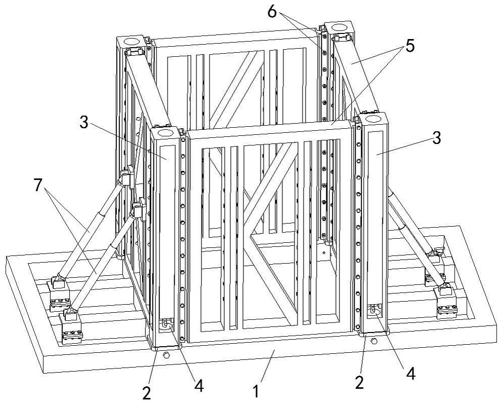
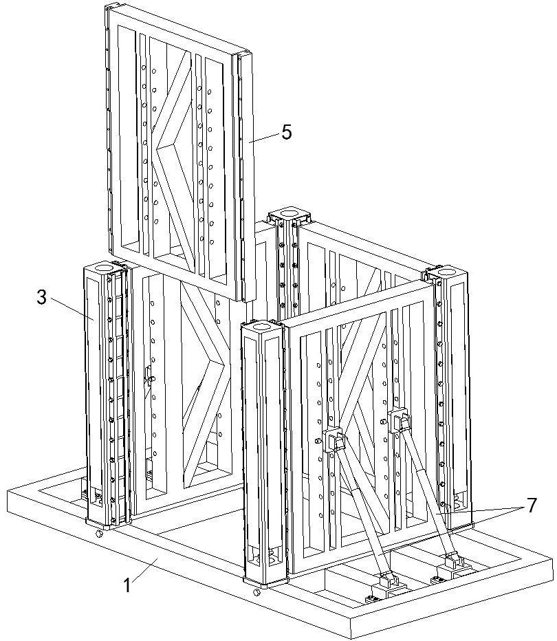
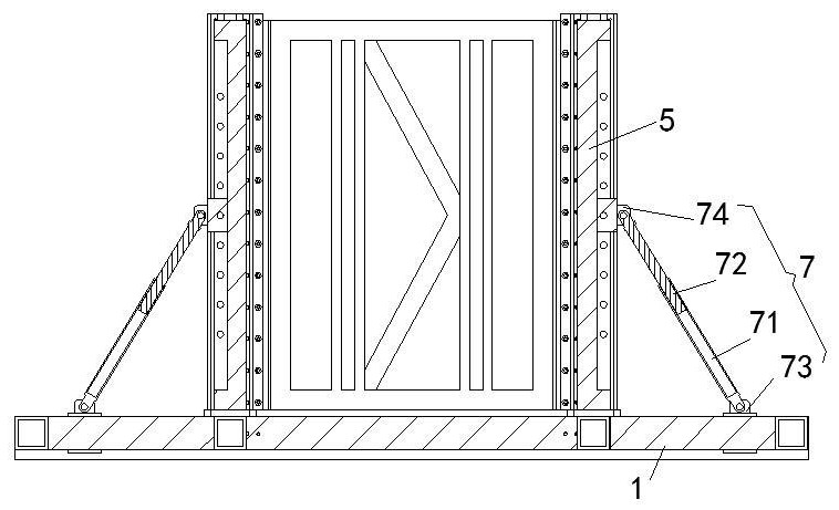
[0027] A kind of assembled steel structure reinforcement bracket of this embodiment, such as Figure 1-Figure 5 As shown, it includes a rectangular reinforced base 1, the four corners of the top rectangular area of the reinforced base 1 are clamped with a transfer support 2, and the top of the transfer support 2 is clamped with a reinforcement column 3. A column tensioning assembly 4 is arranged between the top of the support 2 and the bottom of the reinforcement column 3; the side of the reinforcement column 3 is provided with an assembly groove along the vertical direction, and the assembly on the two adjacent reinforcement columns 3 The support assembly 5 is mounted on sliding cards between the grooves, and the side wall of the assembly groove is provided with a locking device 6 for locking the position of the support assembly 5; An oblique support assembly 7 , one end of the telescopic oblique support assembly 7 is slidingly hinged to the top of the reinforced base 1 , a...
Embodiment 2
[0033] This embodiment is further optimized on the basis of embodiment 1, such as Figure 4 and Figure 5 As shown, the top of the transfer support 2 is provided with a small transfer cone 21, and the top of the transfer cone 21 is provided with a threaded hole for installing the column tensioning assembly 4. The reinforcement The bottom of the upright column 3 is provided with a conical socket that is plugged and joined with the adapter cone 21 .
[0034] Through the cooperation and splicing between the tapered socket at the bottom of the reinforcement column 3 and the transfer cone 21 provided on the top of the transfer support 2, the installation of the reinforcement column 3 on the top of the transfer support 2 is guided, and at the same time, the reinforcement column 3 installs more smoothly. After the bottom end surface of the reinforcement column 3 is in contact with the top end surface of the transfer support 2, it indicates that the reinforcement column 3 is install...
Embodiment 3
[0037] This embodiment is further optimized on the basis of above-mentioned embodiment 1 or 2, such as Figure 4 and Figure 5As shown, the column tensioning assembly 4 is a locking cone 41 with a large top and a small bottom, and the bottom of the locking cone 41 is threadedly connected with the threaded hole of the adapter cone 21 through a connecting stud; There is a conical pressing port coaxial with the conical socket coaxially arranged with the locking cone 41 inside, and the bottom of the conical compressing port is connected with the top of the tapered socket.
[0038] Firstly, the reinforcement column 3 is installed on the top of the transfer support 2, so that the tapered socket at the bottom of the reinforcement column 3 is spliced with the transfer cone 21 at the top of the transfer support 2 to realize the pre-positioning installation of the reinforcement column 3. Then the connecting stud at the bottom of the locking cone 41 can be screwed into the threaded ho...
PUM
 Abstract
Description
Claims
Application Information
 - R&D
- Intellectual Property
- Life Sciences
- Materials
- Tech Scout
- Unparalleled Data Quality
- Higher Quality Content
- 60% Fewer Hallucinations
Browse by: Latest US Patents, China's latest patents, Technical Efficacy Thesaurus, Application Domain, Technology Topic, Popular Technical Reports.
© 2025 PatSnap. All rights reserved.Legal|Privacy policy|Modern Slavery Act Transparency Statement|Sitemap|About US| Contact US: help@patsnap.com