
Scaffold protection equipment for building construction

A technology for building construction and protective equipment, which is applied to the accessories of scaffolding, buildings, building structures, etc. It can solve the problems of equipment work efficiency reduction, direct contact with people or objects, and scratches on sharp ends, etc., and achieves the effect of simple structure

Inactive Publication Date: 2021-02-23
余北京
View PDF5 Cites 0 Cited by
  • Summary
  • Abstract
  • Description
  • Claims
  • Application Information

AI Technical Summary

Problems solved by technology

[0002] Scaffolding is used in the construction of construction projects. Its purpose is to facilitate the construction of construction personnel. Most of the existing scaffolding uses steel pipe structures for construction. During the construction of steel pipes, steel pipes are generally hollow structures, and then the joints of the steel pipe hollow structures are easy. There is a bright gap, which is easy to puncture people, and then because the end of this structure is easy to cause scratches after contact with people, or when the sharp end directly touches people or objects, it will cause damage to people and objects. The existence of the situation will greatly reduce the working efficiency of the equipment, and will cause great damage and threats to personnel and objects, so that the equipment cannot meet the daily needs of personnel and the guarantee of safe work, so that when the equipment is actually used The effect is greatly reduced

Method used


Image

  • Scaffold protection equipment for building construction
  • Scaffold protection equipment for building construction
  • Scaffold protection equipment for building construction

Examples


Embodiment Construction

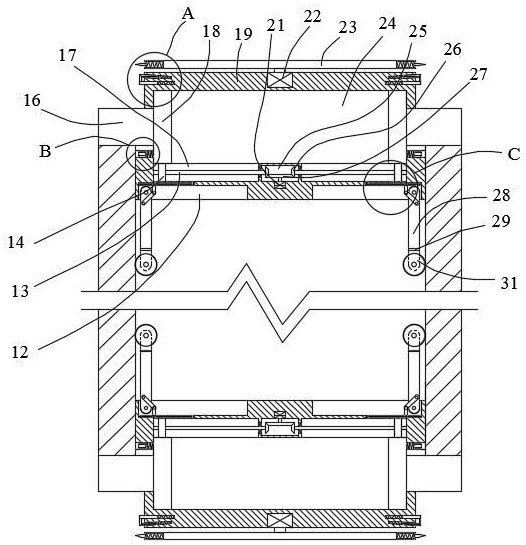
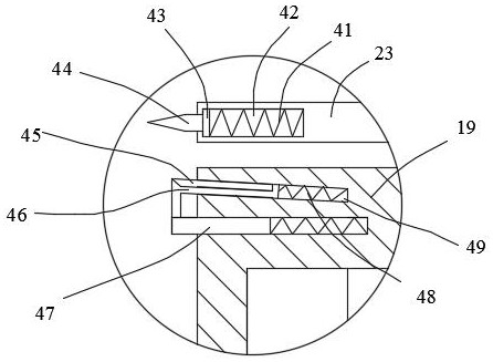
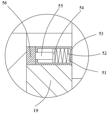
[0025] Such as Figure 1-Figure 4 As shown, the present invention is described in detail. For the convenience of description, the orientations mentioned below are now stipulated as follows: figure 1 The up, down, left, right, front and back directions of the projection relationship are the same. The scaffold protection equipment for building construction of the present invention includes a box body 19. An internal cavity 24 is provided in the box body 19. The top of the box body 19 is provided with a device for making the equipment in the pipeline. A scraping device for scraping the inside of the pipeline, a symmetrical sliding push plate 18 is installed slidingly in the inner cavity 24, and a sliding protrusion 16 is arranged on one side of the sliding pushing plate 18, and the inner One side of the cavity 24 is provided with a bottom moving device that simultaneously drives the sliding push plates 18 on both sides to move, and the other side of the box body 19 is provided wi...


PUM


Abstract

The invention discloses scaffold protection equipment for building construction. The scaffold protection equipment comprises a box body, an inner cavity is formed in the box body, a scraping device used for enabling the equipment to scrape the interior of a pipeline in a pipeline is arranged at the top of the box body, symmetrical sliding push plates are arranged in the inner cavity in a sliding mode, sliding protruding blocks are arranged on one sides of the sliding push plates, a bottom moving device driving the sliding push plates on the two sides to move at the same time is arranged on oneside of the inner cavity, a moving connecting device stretching in the scaffold pipeline in a swinging mode to enable the equipment to move so that the equipment can move to the end opening of the scaffold pipeline to protect can be arranged on the other side of the box body, and a supporting tightening device used for elastically supporting the interior of the pipeline is further arranged in thebox body. The equipment can move in the pipeline of the scaffold, and then the equipment can be unfolded at the positions of two end openings of the pipeline and used for plugging so as to prevent the situation that a breaking notch possibly formed in the pipeline opening punctures an object or hurts people.

Description

technical field [0001] The invention relates to the technical field of scaffolding equipment, in particular to scaffolding protective equipment for building construction. Background technique [0002] Scaffolding is used in the construction of construction projects. Its purpose is to facilitate the construction of construction personnel. Most of the existing scaffolding uses steel pipe structures for construction. During the construction of steel pipes, steel pipes are generally hollow structures, and then the joints of the steel pipe hollow structures are easy. There is a bright gap, which is easy to puncture people, and then because the end of this structure is easy to cause scratches after contact with people, or when the sharp end directly touches people or objects, it will cause damage to people and objects. The existence of the situation will greatly reduce the working efficiency of the equipment, and will cause great damage and threats to personnel and objects, so tha...

Claims


Application Information

Patent Timeline
Patent Type & Authority Applications(China)
IPC IPC(8): E04G5/00
CPCE04G5/00
Inventor 余北京
Owner 余北京
Learn More