Deburring device for cuts of metal round tubes

A technology for deburring and round tubes, which is applied to metal processing equipment, grinding machines, and parts of grinding machine tools. It can solve the problems of low work efficiency and easy injury, and achieve the effect of improving work efficiency.

Active Publication Date: 2018-11-30
江苏成伟管件科技有限公司
View PDF10 Cites 6 Cited by
  • Summary
  • Abstract
  • Description
  • Claims
  • Application Information

AI Technical Summary

Problems solved by technology

[0003] In order to overcome the need for staff to hold the file to continuously file the incision of the metal round tube for deburring, the work efficiency is low, and the shortcomings of easily hurti

Method used


Image

  • Deburring device for cuts of metal round tubes
  • Deburring device for cuts of metal round tubes
  • Deburring device for cuts of metal round tubes

Examples


Example Embodiment

[0016] Example 1

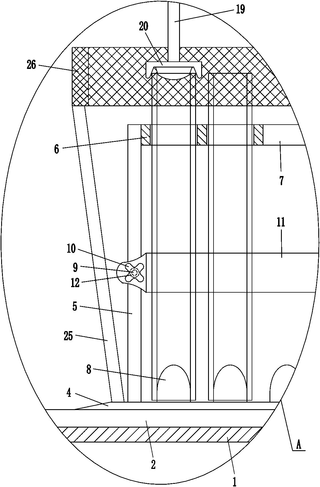
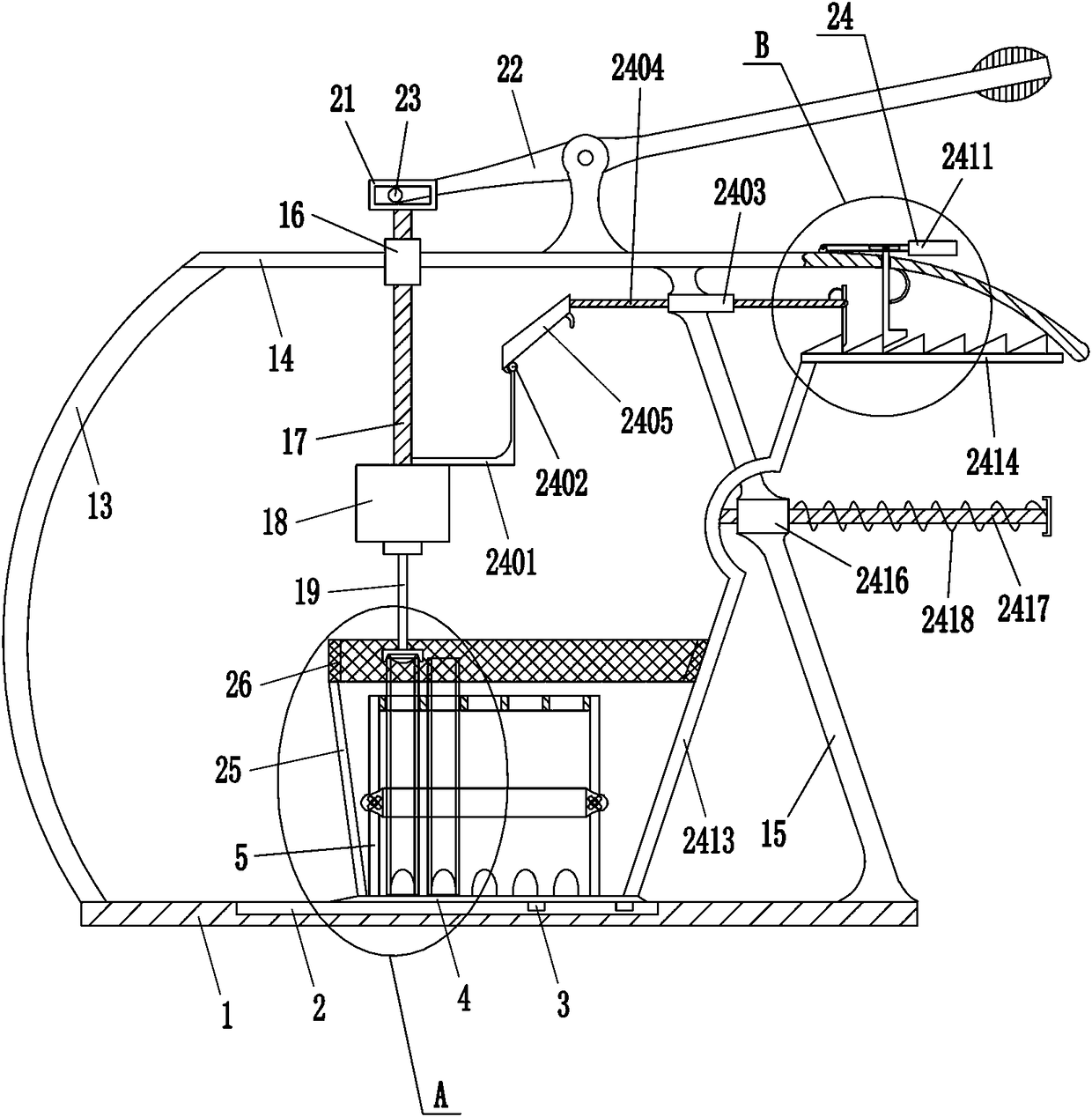
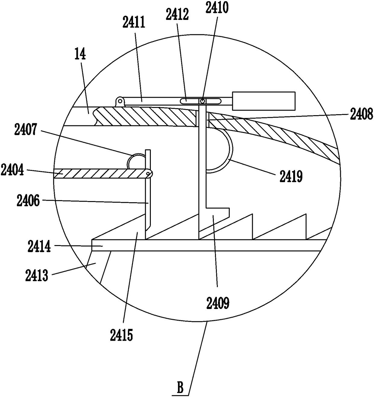
[0017] A metal circular tube incision deburring device, such as Figure 1-3 As shown, it includes a base 1, a slider 3, a support plate 4, a vertical bar 5, a horizontal plate 6, a protrusion 8, a screw 10, a pressure plate 11, an arc bar 13, a top plate 14, an oblique bar 15, a sliding sleeve 16, Slide bar 17, motor 18, rotating shaft 19, polishing block 20, return-shaped frame 21, joystick 22 and roller 23, have chute 2 in the middle of the top of base 1, slide type is provided with two slide blocks 3 in chute 2 , the tops of the two sliders 3 are connected with support plates 4, the top left and right sides of the support plates 4 are connected with vertical bars 5, the upper part between the two vertical bars 5 is connected with horizontal plates 6, and the horizontal plates 6 are evenly spaced with openings Five placement holes 7, five protrusions 8 are evenly spaced connected on the top of the support plate 4, and the five protrusions 8 are all locate...

Example Embodiment

[0018] Example 2

[0019] A metal circular tube incision deburring device, such as Figure 1-3 As shown, it includes a base 1, a slider 3, a support plate 4, a vertical bar 5, a horizontal plate 6, a protrusion 8, a screw 10, a pressure plate 11, an arc bar 13, a top plate 14, an oblique bar 15, a sliding sleeve 16, Slide bar 17, motor 18, rotating shaft 19, polishing block 20, return-shaped frame 21, joystick 22 and roller 23, have chute 2 in the middle of the top of base 1, slide type is provided with two slide blocks 3 in chute 2 , the tops of the two sliders 3 are connected with support plates 4, the top left and right sides of the support plates 4 are connected with vertical bars 5, the upper part between the two vertical bars 5 is connected with horizontal plates 6, and the horizontal plates 6 are evenly spaced with openings Five placement holes 7, five protrusions 8 are evenly spaced connected on the top of the support plate 4, and the five protrusions 8 are all located ...

Example Embodiment

[0021] Example 3

[0022] A metal circular tube incision deburring device, such as Figure 1-3 As shown, it includes a base 1, a slider 3, a support plate 4, a vertical bar 5, a horizontal plate 6, a protrusion 8, a screw 10, a pressure plate 11, an arc bar 13, a top plate 14, an oblique bar 15, a sliding sleeve 16, Slide bar 17, motor 18, rotating shaft 19, polishing block 20, return-shaped frame 21, joystick 22 and roller 23, have chute 2 in the middle of the top of base 1, slide type is provided with two slide blocks 3 in chute 2 , the tops of the two sliders 3 are connected with support plates 4, the top left and right sides of the support plates 4 are connected with vertical bars 5, the upper part between the two vertical bars 5 is connected with horizontal plates 6, and the horizontal plates 6 are evenly spaced with openings Five placement holes 7, five protrusions 8 are evenly spaced connected on the top of the support plate 4, and the five protrusions 8 are all locate...


PUM


Abstract

The invention relates to a deburring device, in particular to a deburring device for cuts of metal round tubes. The invention provides the deburring device for the cuts of the metal round tubes capable of improving the work efficiency and avoiding hands from being hurt. The technical scheme is as follow: the deburring device for the cuts of the metal round tubes comprises a base, two slide blocks,a supporting plate, vertical rods, a transverse plate, a bump, a screw, a pressure plate and the like. A chute is formed in the middle of the top of the base, the two slide blocks are slidably arranged in the chute, the supporting plate is connected to the tops of the slide blocks, the vertical rods are connected to the left and right sides of the top of the supporting plate, and the transverse plate is connected to the upper part between the two vertical rods. The deburring device provided by the invention can be used for deburring five metal round rubes at one time, so that the work efficiency can be improved; staff need not to hold a file to file the cuts of the metal round tubes continuously to deburr the cuts, so that the hands can be prevented from being hurt; the metal round tubescan be transported through a transportation mechanism, and are not transported manually, so that the work efficiency can be further improved.

Description

technical field [0001] The invention relates to a deburring device, in particular to a metal circular tube incision deburring device. Background technique [0002] The metal round tube is a hollow long strip of round steel. In order to facilitate the use of the metal round tube, the metal round tube needs to be cut. After cutting, there will usually be burrs at the incision of the metal round tube. To remove the burrs at the incision of the metal round tube, at present, the staff generally hold the metal round tube with their hands, and then hold the file to continuously file the incision of the metal round tube for deburring, so the work efficiency is low, and the metal round tube The incision of the tube is relatively sharp, which is easy to hurt people's hands; in order to avoid hurting hands, the staff will wear gloves, so that the metal round tube will easily slip off the staff's hands, which is inconvenient to work. Contents of the invention [0003] In order to ove...

Claims


Application Information

Patent Timeline
IPC IPC(8): B24B9/04B24B41/00B24B41/06
CPCB24B9/04B24B41/005B24B41/06
Inventor 袁毅
Owner 江苏成伟管件科技有限公司
Why Eureka
Try Eureka