Indoor vacuum circuit breaker convenient to maintain and install

A technology of vacuum circuit breaker and circuit breaker body, applied to high-voltage air circuit breakers, circuits, electrical components, etc., can solve the problems of reducing work efficiency, inconvenient comprehensive maintenance of circuit breakers, etc., and achieve the effect of easy maintenance

Inactive Publication Date: 2021-02-23
西安鼎腾电子科技有限公司
View PDF1 Cites 0 Cited by
  • Summary
  • Abstract
  • Description
  • Claims
  • Application Information

AI Technical Summary

Problems solved by technology

[0005] The purpose of the present invention is to solve the problem that the circuit breaker in the prior art is not convenient for comprehensive maintenance, thereby reducing the work efficiency, and proposes an indoor vacuum circuit breaker that is convenient for maintenance and installation

Method used


Image

  • Indoor vacuum circuit breaker convenient to maintain and install
  • Indoor vacuum circuit breaker convenient to maintain and install
  • Indoor vacuum circuit breaker convenient to maintain and install

Examples


Embodiment 1

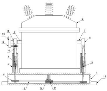
[0023] Embodiment 1, with reference to Figure 1-3 , this indoor vacuum circuit breaker that is easy to maintain and install includes a base 1 and a circuit breaker body 2, the upper surface of the base 1 is fixed with a placement groove 19, the circuit breaker body 2 is located inside the placement groove 19, and the upper surface of the base 1 Sleeves 3 are fixed on the left and right sides of the surface, the first support rod 4 and the second support rod 5 are respectively slidingly arranged inside the two sleeves 3, and the first rotating shaft is fixed on the left and right sides of the circuit breaker body 2 respectively. 6 and the second rotating shaft 7, the ends of the first rotating shaft 6 and the second rotating shaft 7 away from the circuit breaker body 2 are respectively rotatably connected to the rod walls of the first support rod 4 and the second support rod 5 through the first rolling bearing, and the first The end of the rotating shaft 6 is provided with a l...

Embodiment 7

[0029] Embodiment 7, with reference to Figure 1-3 , this indoor vacuum circuit breaker that is easy to maintain and install includes a base 1 and a circuit breaker body 2, the upper surface of the base 1 is fixed with a placement groove 19, the circuit breaker body 2 is located inside the placement groove 19, and the upper surface of the base 1 Sleeves 3 are fixed on the left and right sides of the surface, the first support rod 4 and the second support rod 5 are respectively slidingly arranged inside the two sleeves 3, and the first rotating shaft is fixed on the left and right sides of the circuit breaker body 2 respectively. 6 and the second rotating shaft 7, the ends of the first rotating shaft 6 and the second rotating shaft 7 away from the circuit breaker body 2 are respectively rotatably connected to the rod walls of the first support rod 4 and the second support rod 5 through the first rolling bearing, and the first The end of the rotating shaft 6 is provided with a l...


PUM


Abstract

The invention relates to the technical field of vacuum circuit breakers, and discloses an indoor vacuum circuit breaker convenient to maintain and install. The indoor vacuum circuit breaker comprisesa base and a circuit breaker body, a placement groove is fixedly formed in the upper surface of the base, and the circuit breaker body is located in the placement groove; sleeves are fixedly arrangedat the left and right sides of the upper surface of the base, a first supporting rod and a second supporting rod are slidably arranged in the two sleeves correspondingly, and a first rotating shaft and a second rotating shaft are fixedly arranged at the left side and the right side of the circuit breaker body correspondingly. The ends, away from the circuit breaker body, of the first rotating shaft and the second rotating shaft are rotatably connected with the rod walls of the first supporting rod and the second supporting rod through first rolling bearings correspondingly, a limiting mechanism is arranged at the end of the first rotating shaft, and lead screws are arranged at the lower ends of the first supporting rod and the second supporting rod in a threaded mode. According to the circuit breaker, the circuit breaker body can be lifted upwards, the circuit breaker body can be rotated by an angle, and a worker can maintain the circuit breaker body conveniently.

Description

technical field [0001] The invention relates to the technical field of vacuum circuit breakers, in particular to an indoor vacuum circuit breaker which is convenient for maintenance and installation. Background technique [0002] Vacuum circuit breaker is named for its arc extinguishing medium and the insulation medium of the contact gap after arc extinguishing are high vacuum. It is widely used in distribution network. Vacuum circuit breaker is a 3-10kV, 50Hz three-phase AC system. The indoor power distribution device can be used for the protection and control of electrical equipment in industrial and mining enterprises, power plants, and substations, and is especially suitable for places that require no oil, less maintenance, and frequent operations. However, most of the indoor vacuum circuit breakers are now installed in a fixed connection, and the circuit breaker and the installation frame are welded together. This setting makes it very inconvenient for the staff to regu...

Claims


Application Information

Patent Timeline
Patent Type & Authority Applications(China)
IPC IPC(8): H01H33/662
CPCH01H33/66207
Inventor 宋鹏飞
Owner 西安鼎腾电子科技有限公司
Why Eureka
Try Eureka