Cabinet type trigger loop device

A technology of trigger circuit and trigger device, which is applied in the direction of panel/switch station circuit device, substation/power distribution device shell, circuit, etc., which can solve problems such as low efficiency of maintenance and debugging, difficulty of maintenance and maintenance, and mutual interference of signals. To achieve the effect of convenient maintenance or other operations, convenient operation and reasonable overall layout

Pending Publication Date: 2021-08-06
CHANGZHOU BORI ELECTRIC POWER AUTOMATION EQUIP +2
View PDF0 Cites 0 Cited by
  • Summary
  • Abstract
  • Description
  • Claims
  • Application Information

AI Technical Summary

Problems solved by technology

[0003] The trigger circuit device is often installed following the position of the high-speed electromagnetic mechanical switch, and its space is very limited. In the existing trigger circuit device, all the lines and components are inside the trigger circuit housing, and the signals will interfere with each other, affecting reliability. It is difficult to overhaul and maintain. If overhaul and debugging are required, the trigger circuit needs to be dismantled separately, and the whole shell is opened for overhaul. The efficiency of overhaul and debugging is low, which is not conducive to the development of corresponding work.

Method used


Image

  • Cabinet type trigger loop device
  • Cabinet type trigger loop device
  • Cabinet type trigger loop device

Examples


Embodiment Construction

[0039] In order to make the content of the present invention more clearly understood, the present invention will be further described in detail below based on specific embodiments and in conjunction with the accompanying drawings.

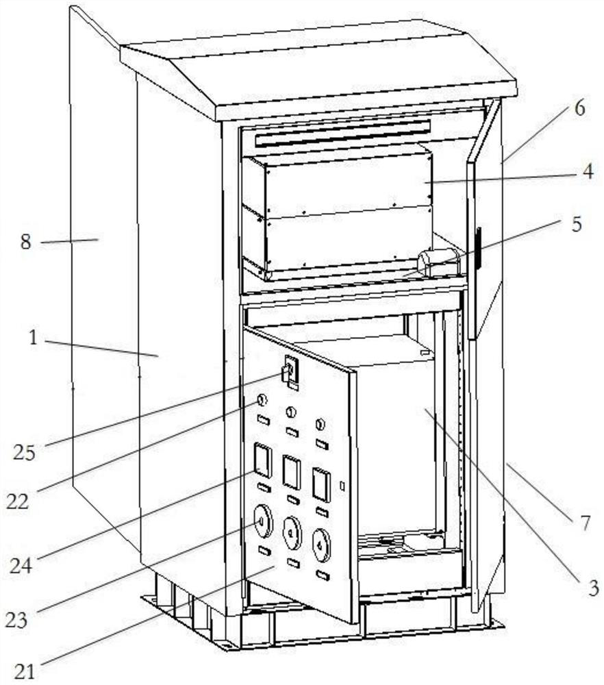
[0040] Such as figure 1 , 2 , Shown in 3, a kind of cabinet trigger circuit device, it comprises cabinet body 1, control panel, energy storage trigger device 3, board card control circuit 4 and charging and discharging circuit; Wherein,

[0041] The inside of the cabinet 1 is divided into an upper cavity and a lower cavity juxtaposed up and down by a metal baffle 5;

[0042] The board control circuit 4 is installed in the upper cavity;

[0043] The control panel is hinged in the lower cavity, and the energy storage trigger device 3 and the charging and discharging circuit are respectively installed in the lower cavity.

[0044] In this embodiment, the charging and discharging circuit includes a charging circuit and a discharging circuit, and the...


PUM


Abstract

The invention discloses a cabinet type trigger loop device which comprises a cabinet body, a control panel, an energy storage trigger device, a board card control loop and a charging and discharging loop; the interior of the cabinet body is divided into an upper cavity and a lower cavity which are parallel up and down by a metal baffle; the board card control loop is mounted in the upper cavity; the control panel is hinged in the lower cavity, and the energy storage trigger device and the charging and discharging loop are respectively installed in the lower cavity. The cabinet type trigger loop device is assembled independently from a high-speed electromagnetic mechanical switch, the space in the cabinet body is separated by adopting the metal baffle, the metal baffle forms a shielding layer, the board card control loop is protected from being influenced by high-voltage current generated by the energy storage trigger device and the charging and discharging loop, and the reliability is high.

Description

technical field [0001] The invention relates to a cabinet type trigger circuit device. Background technique [0002] High-voltage DC circuit breaker is the core equipment for constructing multi-terminal flexible DC system, and its existence can effectively improve the reliability and economy of system operation. The high-speed electromagnetic mechanical switch is an important part of the circuit breaker, and the trigger circuit provides the required pulse current for the high-speed electromagnetic mechanical switch, which is the key to ensure the successful operation of the high-speed electromagnetic mechanical switch. [0003] The trigger circuit device is often installed following the position of the high-speed electromagnetic mechanical switch, and its space is very limited. In the existing trigger circuit device, all the lines and components are inside the trigger circuit housing, and the signals will interfere with each other, affecting reliability. It is difficult to ...

Claims


Application Information

Patent Timeline
Patent Type & Authority Applications(China)
IPC IPC(8): H02B1/30H02B1/32H02B1/24H01H9/54
CPCH01H9/54H02B1/24H02B1/30H02B1/32
Inventor 姚宁韩玉辉陈新王智勇许元震陈羽孙超
Owner CHANGZHOU BORI ELECTRIC POWER AUTOMATION EQUIP
Why Eureka
Try Eureka