Inductive rotation angle sensor and motor-driven airflow control device using the same

一种旋转检测、控制装置的技术,应用在发动机控制、测量装置、采用电/磁装置传递传感构件等方向,能够解决装置变大、氧化、电磁感应作用变弱等问题

Active Publication Date: 2008-04-16
HITACHI ASTEMO LTD
View PDF3 Cites 24 Cited by
  • Summary
  • Abstract
  • Description
  • Claims
  • Application Information

AI Technical Summary

Problems solved by technology

[0008] In the conventional non-contact rotation angle detection device, it is necessary to install a magnetic disk and a conductor disk, and between two sets of detection coils arranged on the stator, one is installed on the rotating body and the other is installed on the stator. There is a problem that the device becomes larger
[0009] In addition, when the latter conventional technology is used in a motor-driven throttle valve control device, the substrate on which the electronic components are mounted is exposed to moisture and chemical substances from the intake passage, or wear to the gears and bearings. Among powders, resin powder or metal powder, there is a possibility of oxidation, corrosion, or electromagnetic deterioration.
Therefore, it is necessary to consider the problem of decreased reliability due to such reasons
[0010] In addition, if the gap between the rotating conductor and the substrate having the fixed (detection) side coil part becomes large, the electromagnetic induction effect will be weakened, and the position detection accuracy may deteriorate.

Method used


Image

  • Inductive rotation angle sensor and motor-driven airflow control device using the same
  • Inductive rotation angle sensor and motor-driven airflow control device using the same
  • Inductive rotation angle sensor and motor-driven airflow control device using the same

Examples


Embodiment 1

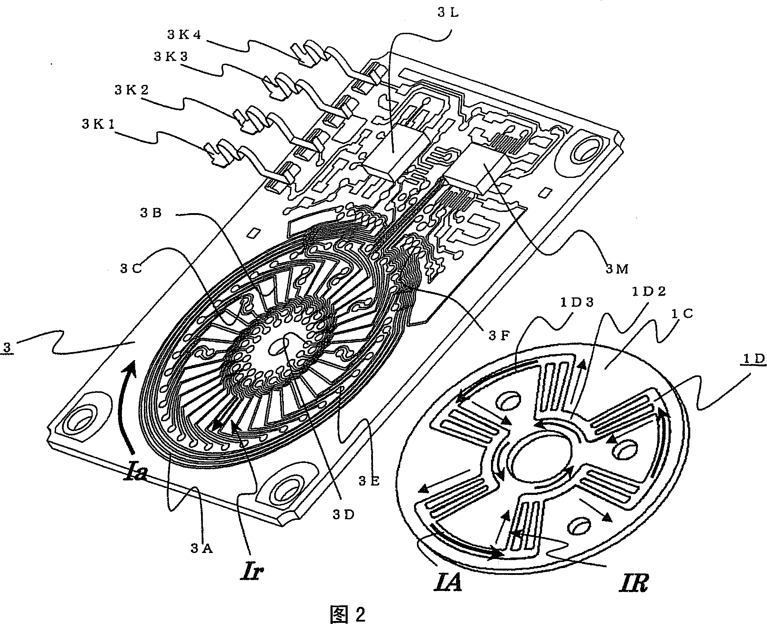
[0043] One embodiment of the rotation angle detecting device of the present invention will be described with reference to FIGS. 1 and 2 .

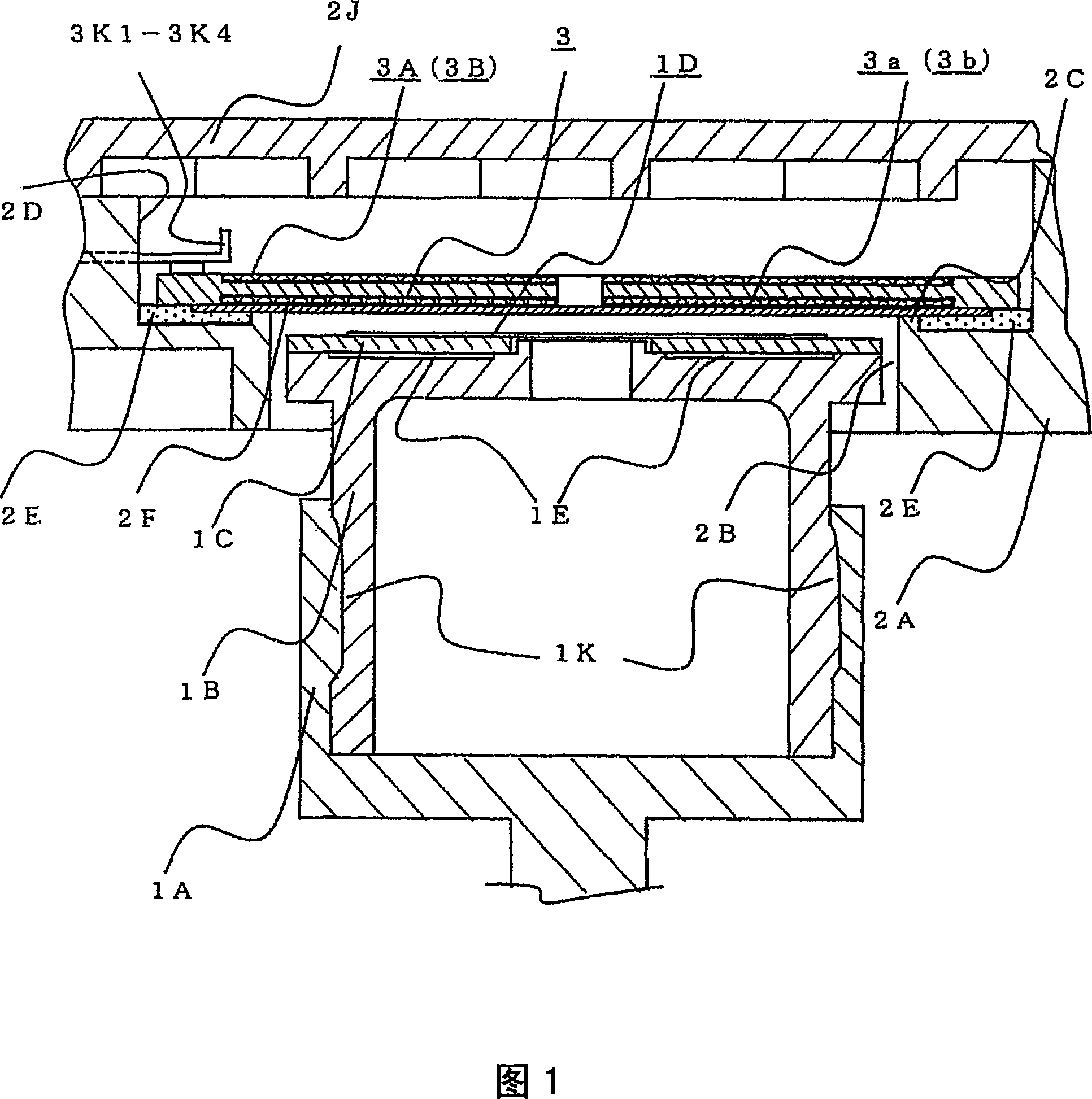
[0044] As shown in FIG. 1 , a shallow cylindrical (cup-shaped) holder 1B made of a resin molded body is attached to the front end of the rotating shaft 1A. A circular plate 1C made of insulating material is bonded and fixed to the front end surface of the bracket 1B. An annular recess 1E is formed on the front end surface of the holder 1B, and the adhesive flows into the recess 1E, and the disc 1C is placed on the upper surface and bonded. An excitation conductor 1D to be described later is printed on the surface (the surface opposite to the bonding surface) of the circular plate 1C.

[0045] Grooves extending in the axial direction are formed around the cylindrical portion of the bracket 1B, and ridges extending in the axial direction are formed alternately with the grooves on the inner peripheral surface of the rotating body 1A, and the...

Embodiment 2

[0104] An alternative structure of the fixing structure of the fixing substrate 27 will be described with reference to FIG. 10 .

[0105] Positioning pins 36 are provided on the gear cover 25 .

[0106] The positioning pin 36 is provided with a notch 37 , and the diameter of the positioning pin 36 may be larger than the diameter of the installation hole provided on the fixed base 27 .

[0107] By employing this structure, the fixing base plate 27 can be fixed to the gear cover 25 by the resin elastic force of the positioning pin 36 acting on the mounting hole of the fixing base plate 27 .

[0108] On the other hand, a drop prevention pin 38 is provided on the resin cover 29 .

[0109] A hole slightly larger than that of the positioning pin 36 is provided in the anti-dropout pin 38 , and the positioning pin 36 and the anti-dropout pin 38 are coupled by coupling the resin cover 29 to the gear cover 25 .

[0110] There is a certain gap between the anti-dropping pin 38 and the f...

Embodiment 3

[0112] As shown in FIG. 11 , immediately after the gear cover 25 is resin-molded, the gear storage chamber 30 and the substrate mounting space 31 are connected to each other.

[0113] At this connecting portion, the thin resin plate 28 is fixed to the gear cover 25 with an adhesive 33 to close the window hole. Thereby, the gear storage chamber 30 and the board|substrate mounting part space 31 are isolate|segregated. Then, the thin resin plate 28 and the fixed substrate 27 are fixed with the adhesive 33 in the same manner. After connecting the gear cover 25 and electrically connecting the fixed substrate 27 , the resin cover 29 is fixed to the gear cover 25 with an adhesive 33 to block the outside air from the substrate mounting space 31 .

[0114] The above-mentioned embodiment described the method of bonding the thin-walled resin plate 28 to the gear cover 25, but it may also be bonded to the fixed substrate 27, and then the fixed substrate 27 assembled with the thin-walled ...


PUM


Abstract

A motor-driven airflow control device is provided wherein an inductance-based non-contact rotation angle sensor is compactly formed at an end of a throttle shaft. An exciting conductor is attached at an end of a rotating shaft to which a throttle valve is attached, a window hole is provided on a gear cover, a stationary substrate with energizing and signal-generating conductors formed thereon is attached to the gear cover so as to face the exciting conductor on the rotating shaft side through the window hole, and the window hole of the gear cover is covered by a thin shield member. The energizing and signal-generating conductors can be shielded from a space where the exciting conductor of the rotary member is arranged, making it possible to obtain a highly reliable motor-driven airflow control device including an inductance-based non-contact rotation angle sensor which is not affected by environments on the rotary member side.

Description

technical field [0001] The present invention relates to a rotation angle detecting device, which detects that the inductance between the conductor installed on the rotating shaft of the rotating body and the coil conductor installed on the facing stator corresponds to the positional relationship between the two. The rotated position of the rotated conductor. [0002] It also relates to a motor-driven throttle control device that electrically controls the opening area of ​​an air passage of an internal combustion engine using a throttle valve driven by a motor, and includes the above-mentioned rotation angle detection device for detecting the rotation angle of the throttle valve. Background technique [0003] As a so-called non-contact rotation angle detection device that detects the position or rotation angle of a rotating body by a change in inductance, a device described in Japanese Patent Application Laid-Open No. 2003-254782 is known. [0004] This rotation angle detect...

Claims


Application Information

Patent Timeline
Patent Type & Authority Applications(China)
IPC IPC(8): G01D5/20F02D9/10
CPCG01D5/2086G01D5/2073G01D5/208F02D9/105Y10T137/8242
Inventor 初泽英文志村隆弘曾筱雅彦
Owner HITACHI ASTEMO LTD
Why Eureka
Try Eureka