Outdoor waterproof PLC control box

A technology for controlling boxes and lights, which can be applied to casings/cabinets/drawer components, electrical equipment casings/cabinets/drawers, electrical components, etc., and can solve problems such as inconvenient adjustment of waterproof boards and reduced device practicability , to achieve the effect of improving replacement efficiency, improving practicability, and improving adjustment effect

Inactive Publication Date: 2021-02-23
XIAN LANXIN IND AUTOMATION ENG CO LTD
View PDF0 Cites 0 Cited by
  • Summary
  • Abstract
  • Description
  • Claims
  • Application Information

AI Technical Summary

Problems solved by technology

[0005] The purpose of the present invention is to provide an outdoor waterproof PLC control box to solve the traditional outdoor PLC control box proposed in the above background technology, the waterproof board is inconvenient to adjust, and the waterproof board has limitations during use, which reduces the practicability of the device question

Method used


Image

  • Outdoor waterproof PLC control box
  • Outdoor waterproof PLC control box
  • Outdoor waterproof PLC control box

Examples


Embodiment 1

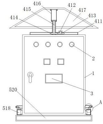
[0022] Embodiment 1. An outdoor waterproof PLC control box, including a box body 1, a control light 2 and a display screen 3, the front end of the box body 1 is provided with a control light 2, and the front end of the box body 1 is equipped with a display screen 3, and the control light 2 can be It is convenient for the staff to directly observe the circuit fault problem, and the display screen 3 can observe the use of the cabinet 1;

Embodiment 2

[0023] Embodiment 2. The top of the box body 1 is provided with a waterproof device, and the waterproof device includes a fixed plate 411, a threaded rod 415, a sleeve 416 and a waterproof plate 417. The top of the box body 1 is fixedly connected to the fixed plate 411, and the inside of the fixed plate 411 A threaded rod 415 is embedded, and the outer wall of the top end of the threaded rod 415 is sleeved with a sleeve 416, and the top end of the sleeve 416 is connected with a waterproof plate 417 through a bearing. The waterproof device also includes a handle 412, a first gear 413 and a second gear 414, and a fixed plate 411 top is provided with handle 412 and handle 412 is connected with first gear 413 through bearing, and first gear 413 meshes with second gear 414, and second gear 414 is welded on threaded rod 415 outer wall, sleeve 416 bottom end inner wall is provided with inner thread, and the internal thread and the external thread of the threaded rod 415 coincide with ...

Embodiment 3

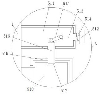
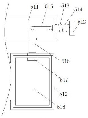
[0024] Embodiment 3, the bottom end of the box body 1 is provided with a mounting mechanism, the mounting mechanism includes a fixed block 511, a switch 512, a movable rod 513, a spring 514, a hinged rod 515, a clamping block 516, a clamping groove 517, a sliding block 518, and a sliding groove 519 and the moisture-proof plate 520, the left and right sides of the bottom of the box body 1 are fixedly connected with fixed blocks 511, the two sets of fixed blocks 511 are provided with switches 512 on the opposite sides, and the opposite sides of the two sets of switches 512 are fixedly connected with movable rods 513 The outer walls of the two groups of movable rods 513 are wound with springs 514, and the opposite sides of the two groups of movable rods 513 are hinged with clamping blocks 516 through hinged rods 515, and the bottom ends of the clamping blocks 516 are embedded in the inside of the clamping groove 517, and the shape of the clamping blocks 516 and The draw-in slot 51...


PUM


Abstract

An outdoor waterproof PLC control box disclosed by the present invention comprises a box body, a control lamp and a display screen, the control lamp is arranged at the front end of the box body, and the display screen is installed at the front end of the box body. A waterproof device is arranged at the top end of the box body, the waterproof device comprises a fixed plate, a threaded rod, a sleeveand a waterproof plate, and the top end of the box body is fixedly connected with the fixed plate. A threaded rod is embedded in the fixed plate, the outer wall of the top end of the threaded rod issleeved with a sleeve, and a mounting mechanism is arranged at the bottom end of the box body. A handle is rotated to drive a first gear and a second gear to rotate, the threaded rod rotates at the moment, the sleeve is made to rotate gradually and move upwards under the action of the threads, and therefore the waterproof plate is pushed to move upwards, and the adjusting effect of the device canbe improved in this way. The waterproof plate can comprehensively shield the box body when being used in rainy days, and meanwhile, the opening process of the box body cannot be hindered when the device needs to be used, and the practicability of the device is improved.

Description

technical field [0001] The invention relates to the technical field of PLC control boxes, in particular to an outdoor waterproof PLC control box. Background technique [0002] There are generally multiple sets of relays inside the PLC control box, which can be used to control the entire circuit to ensure that people use electricity normally, and now the control box is also used for outdoor use. The current outdoor PLC control box basically meets people's needs, but there are still some problems. . [0003] In the current outdoor PLC control box, the top of the control box is generally equipped with a waterproof board. When it is used in rainy days, the rainwater can flow through the waterproof board to prevent rainwater from directly entering the inside of the box. However, the current waterproof board is generally inconvenient to adjust. When using the waterproof board When the setting is higher, the waterproof effect is poor, and when the waterproof plate is set lower, it...

Claims


Application Information

Patent Timeline
Patent Type & Authority Applications(China)
IPC IPC(8): H05K5/02
CPCH05K5/0204H05K5/0217H05K5/0234
Inventor 肖传军
Owner XIAN LANXIN IND AUTOMATION ENG CO LTD
Why Eureka
Try Eureka