Labeling machine
A labeling machine and labeling technology, applied in the direction of labeling machine, labeling, labeling, etc., can solve the problems of low labeling efficiency, inconvenient glass bottle labeling, etc., and achieve the effect of high labeling efficiency
- Summary
- Abstract
- Description
- Claims
- Application Information
AI Technical Summary
Problems solved by technology
Method used
Image
Examples
specific Embodiment approach 1
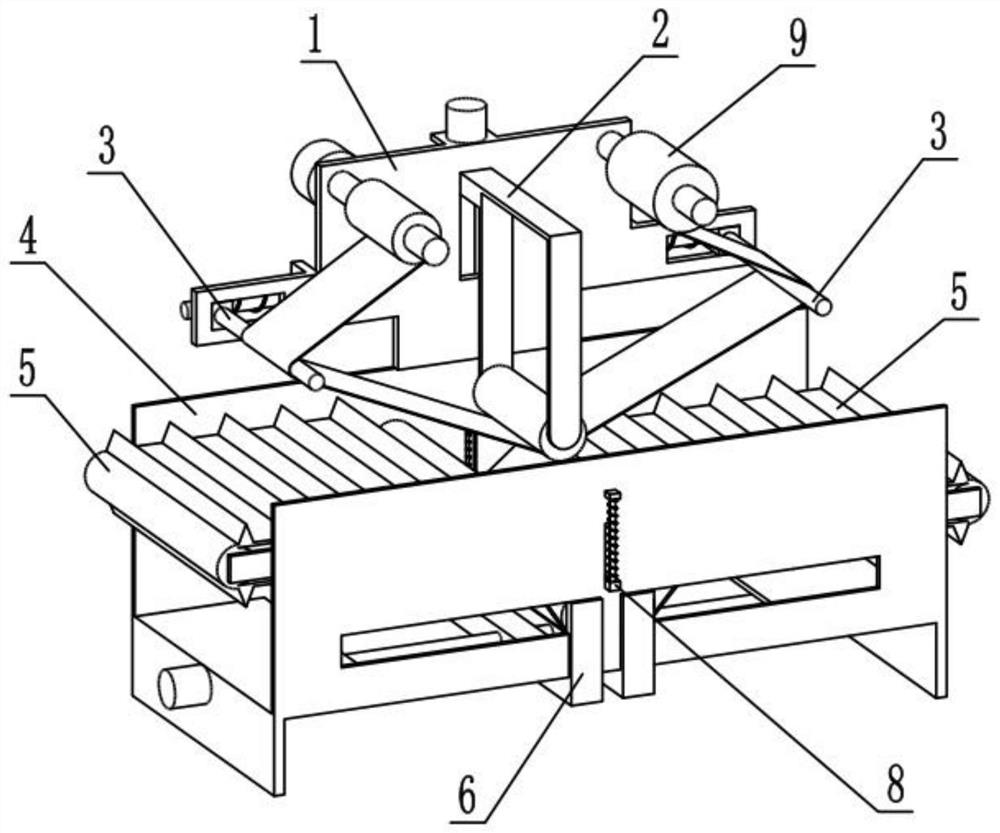
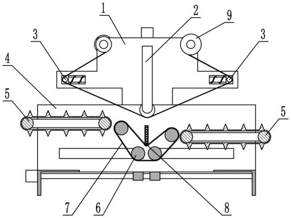
[0028] like Figure 1-10 As shown, the labeling machine includes an upper mounting frame 1, a labeling roller mechanism 2, a labeling support mechanism 3, a lower support frame 4, a conveying mechanism 5, a supporting belt adjusting mechanism 6, a labeling supporting belt 7, a supporting belt tensioner Tightening mechanism 8 and labeling tape 9, the upper mounting frame 1 is fixedly connected to the lower support frame 4, the labeling roller mechanism 2 is connected to the middle of the upper mounting frame 1, the labeling support mechanism 3 There are two, two label support mechanisms 3 are respectively connected to the front and rear ends of the upper mounting frame 1, the label tape 9 is connected to the upper mounting frame 1, the two label support mechanisms 3 Both the labeling roller mechanism 2 and the labeling roller mechanism 2 are pressed against the labeling belt 9. The conveying mechanism 5 is provided with two. The two conveying mechanisms 5 are respectively fixed...
specific Embodiment approach 2
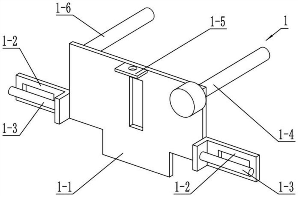
[0031] like Figure 1-10 As shown, the upper mounting frame 1 includes an upper mounting plate 1-1, a side support lug plate 1-2, a sliding column 1-3, a winding installation roller 1-4, a motor mounting plate 1-5 and a label tape Roll the installation rollers 1-6, the front and rear ends of the upper installation plate 1-1 are fixedly connected with side support lugs 1-2, and the two side support lugs 1-2 are fixedly connected with slide columns 1-3, The roll mounting roller 1-4 is connected to the front end of the upper mounting plate 1-1 in rotation, the label tape roll mounting roller 1-6 is rotated and connected to the rear end of the upper mounting plate 1-1, and the motor mounting plate 1-5 is fixedly connected to the upper mounting plate 1-1. Mounting plate 1-1 and the output shaft are fixedly connected to the winding installation roller 1-4, the motor mounting plate 1-5 is fixedly connected to the upper end of the upper mounting plate 1-1, and the label tape 9 is fixe...
specific Embodiment approach 3
[0034] like Figure 1-10As shown, the labeling roller mechanism 2 includes a labeling roller 2-1, a labeling roller frame 2-2, a threaded block 2-3, a lifting motor 2-4 and a lifting threaded rod 2-5. The labeling roller 2 -1 Rotately connected to the lower end of the labeling roller frame 2-2, the upper end of the labeling roller frame 2-2 is fixedly connected to the threaded block 2-3, and the lifting threaded rod 2-5 is threadedly connected to the threaded block 2-3 , the upper end of the lifting threaded rod 2-5 is fixedly connected to the output shaft of the lifting motor 2-4, the threaded block 2-3 is slidably connected to the upper mounting plate 1-1, and the lifting motor 2-4 is fixedly connected to the motor mounting plate 1 On -5, the labeling roller 2-1 is pressed against the labeling belt 9.
[0035] The labeling roller 2-1 is used to press down the labeling tape 9, and is driven by the lifting motor 2-4 to drive the lifting threaded rod 2-5 to rotate, and the lif...
PUM
 Abstract
Description
Claims
Application Information
 - R&D
- Intellectual Property
- Life Sciences
- Materials
- Tech Scout
- Unparalleled Data Quality
- Higher Quality Content
- 60% Fewer Hallucinations
Browse by: Latest US Patents, China's latest patents, Technical Efficacy Thesaurus, Application Domain, Technology Topic, Popular Technical Reports.
© 2025 PatSnap. All rights reserved.Legal|Privacy policy|Modern Slavery Act Transparency Statement|Sitemap|About US| Contact US: help@patsnap.com


