A coplanar antenna with directional radiation along the surface of the carrier

A technology of directional radiation and carrier surface, which is applied to antennas, resonant antennas, antenna components, etc., can solve the problems of low gain, large size, and lack of flexible design of reflectors, and achieve stable electrical performance, easy mass production, and simple structure Effect

Active Publication Date: 2022-05-17
XIDIAN UNIV +1
View PDF17 Cites 0 Cited by
  • Summary
  • Abstract
  • Description
  • Claims
  • Application Information

AI Technical Summary

Problems solved by technology

In the prior art, there is also the technology of using the microstrip antenna working on the main mode as a unit to form directional radiation technology, but the directional radiation antenna composed of the microstrip antenna working on the main mode has obvious beam upturning when the metal floor is large, and the gain in the horizontal plane lower
In recent years, units equivalent to magnetic current radiation have been applied to solve the above technical problems, but there are still problems of large size and lack of flexible design of reflectors, so a coplanar antenna that radiates directional along the surface of the carrier is proposed. Great practical application value

Method used


Image

  • A coplanar antenna with directional radiation along the surface of the carrier
  • A coplanar antenna with directional radiation along the surface of the carrier
  • A coplanar antenna with directional radiation along the surface of the carrier

Examples


Embodiment Construction

[0036] Now in conjunction with embodiment, accompanying drawing, the present invention will be further described:

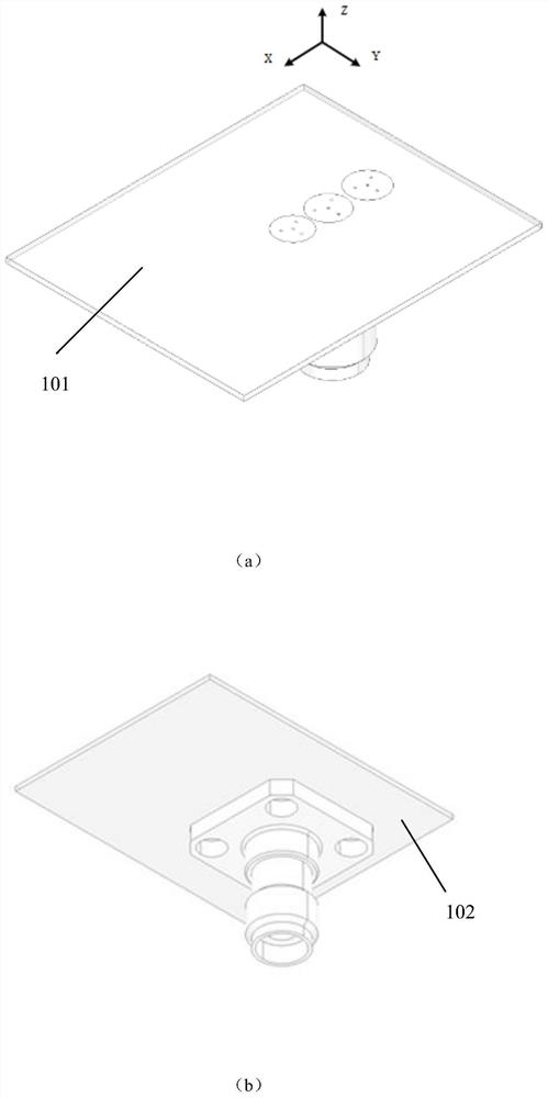
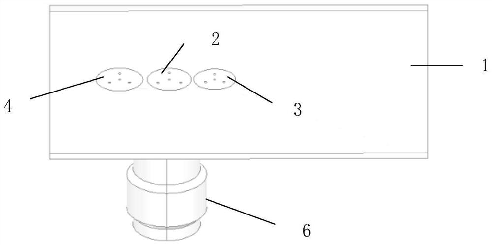
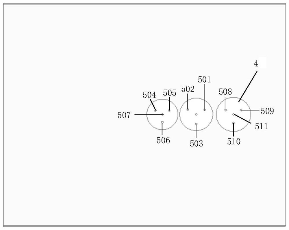
[0037] The coplanar antenna proposed by the present invention directional radiation along the surface of the carrier includes the following parts:

[0038] Dielectric substrate;

[0039] An active radiator patch, the active radiator patch covering the upper surface of the dielectric substrate;

[0040] A director patch, the director patch is covered on the upper surface of the dielectric substrate;

[0041] A reflector patch, the reflector patch covering the upper surface of the dielectric substrate;

[0042] Metal short-circuit pins, the metal short-circuit pins are distributed between the patch on the upper surface of the dielectric substrate and the metal cladding (floor) on the lower surface;

[0043] A radio frequency cable socket, the radio frequency cable socket is placed on the lower surface of the dielectric substrate.

[0044] In the solution, one s...


PUM


Abstract

The invention relates to a coplanar antenna with directional radiation along the surface of a carrier, belonging to the technical field of antennas. Including: dielectric substrate, active radiator patch, director patch, reflector patch, metal shorting pin and RF cable socket. The active radiator patch, the director patch and the reflector patch are all attached to one side of the dielectric substrate (the side facing the outside of the carrier surface); the other side of the dielectric substrate is covered with copper, and the RF cable socket is welded on this side. One side, and located on the back of the active radiator patch, feed the active radiator patch from the bottom, the feeding position is at the center of the patch, and the coplanar antenna of the present invention can be embedded in the surface of the carrier for directional radiation Coplanar design with carrier.

Description

technical field [0001] The invention belongs to the technical field of antennas, and in particular relates to a coplanar antenna with directional radiation along the surface of a carrier, which forms vertical polarization (perpendicular to the surface of the carrier) directional radiation in a tangential direction along the surface of the carrier. Background technique [0002] It is often necessary to install multiple antennas with different functions on a high-speed moving carrier, such as navigation, communication, radar, and altimetry antennas. At present, most of these antennas are exposed antennas, which will not only affect the aerodynamic performance of the carrier, but also cause conflicts in the assembly position, resulting in physical shielding and electromagnetic compatibility problems. Coplanar antennas have unique advantages in solving the above problems. [0003] The coplanar antenna can be coplanarly designed with complex carriers of various shapes, and becom...

Claims


Application Information

Patent Timeline
Patent Type & Authority Patents(China)
IPC IPC(8): H01Q9/04H01Q1/50H01Q1/24
CPCH01Q9/0407H01Q1/50H01Q1/241
Inventor 傅光周祺磊牛传峰陈曦
Owner XIDIAN UNIV
Why Eureka
Try Eureka