
Horizontal flapping wing low-altitude aircraft

A low-altitude aircraft, flat shooting technology, applied in the field of aircraft, can solve problems such as limited application scope and the need for taxiing distance on the take-off runway.

Inactive Publication Date: 2021-03-02
GUANGDONG GUOSHIJIAN TECH DEV CO LTD
View PDF6 Cites 0 Cited by
  • Summary
  • Abstract
  • Description
  • Claims
  • Application Information

AI Technical Summary

Problems solved by technology

Its advantage is that it has lower requirements on the take-off runway but still needs to glide distance, and it cannot hover in the air. The application range is limited

Method used


Image

  • Horizontal flapping wing low-altitude aircraft
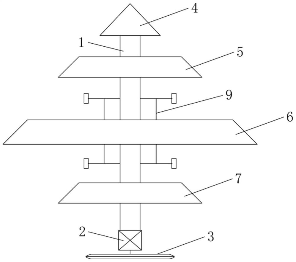
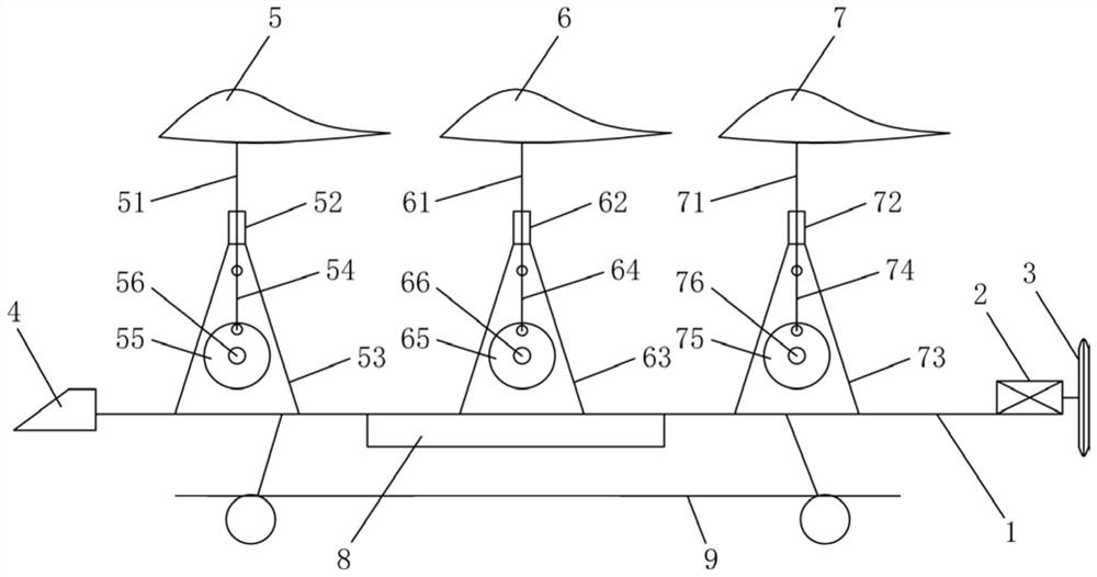
  • Horizontal flapping wing low-altitude aircraft
  • Horizontal flapping wing low-altitude aircraft

Examples


Embodiment Construction

[0021] The technical solutions of the present invention will be described below in conjunction with the accompanying drawings and embodiments.

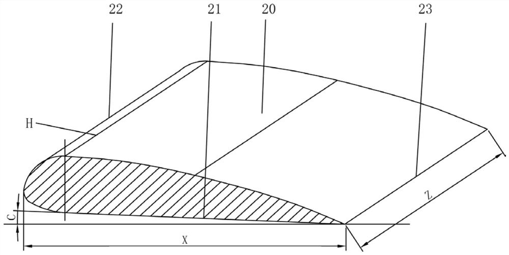
[0022] like figure 1 As shown, a kind of flat flap wing low-altitude aircraft of the present invention comprises frame 1, and frame 1 front end is provided with nose 4, and frame 1 tail end is provided with propulsion device, is provided with between nose 4 and propulsion device successively. The first flying unit, the second flying unit and the third flying unit, the second flying unit is set at the center between the first flying unit and the third flying unit, and is set at the center of gravity of the frame 1, on the frame 1 A control circuit 8 is provided, and the first flying unit, the second flying unit and the third flying unit are respectively controlled by the control circuit 8, and the first flying unit and the third flying unit move up and down synchronously, and alternate up and down with the second flying unit . The ab...


PUM


Abstract

The invention relates to the technical field of aircrafts, in particular to a horizontal flapping wing low-altitude aircraft which comprises a rack, a nose is arranged at the front end of the rack, apropelling device is arranged at the tail end of the rack, and a first flight unit, a second flight unit and a third flight unit are sequentially arranged between the nose and the propelling device. The second flight unit is arranged in the center between the first flight unit and the third flight unit and arranged at the gravity center of the rack, a control circuit is arranged on the rack, the first flight unit, the second flight unit and the third flight unit are controlled through the control circuit, and the first flight unit and the third flight unit ascend and descend synchronously. Andthe second flight unit performs up-and-down staggered lifting action. By the adoption of the structural arrangement, under the matching action of the first flight unit, the second flight unit and thethird flight unit, lift force is generated to achieve takeoff of the aircraft, advancing is achieved under the action of the propelling device, and the aircraft is compact in structure, low in cost and capable of achieving the low-altitude flight effect.

Description

technical field [0001] The invention relates to the technical field of aircraft, in particular to a flapping-wing low-altitude aircraft. Background technique [0002] The lift device of an aircraft is a device based on aerodynamics. According to the structure, it can be divided into fixed wings and rotors. Fixed wing aircraft generally have a fuselage and symmetrically arranged fixed wings, which are powered by propellers to obtain greater flight speeds. and mobility. The principle of flight is that there is a relative speed between the fixed wing and the air, and the air interacts with the sides of the fixed wing to generate lift so that the aircraft obtains flight capability. The disadvantage of fixed-wing aircraft is that it cannot hover in the air, and needs to taxi on the runway to take off or land and support the construction of airport facilities. A rotorcraft such as a helicopter is characterized in that it does not need a runway when it takes off and can hover in ...

Claims


Application Information

Patent Timeline
IPC IPC(8): B64C3/58B64C19/00B64C27/08B64C27/32B64C27/46B64D27/24B64D35/00
CPCB64C3/58B64C19/00B64C27/08B64C27/32B64C27/46B64D27/24B64D35/00
Inventor 王志成
Owner GUANGDONG GUOSHIJIAN TECH DEV CO LTD
Learn More