
Dielectric waveguide filter

A dielectric waveguide and filter technology, which is applied in the field of communication equipment components, can solve the problems affecting the selectivity of ceramic dielectric filters and the difficulty of adding negative coupling structures.

Pending Publication Date: 2021-03-02
人民华智通讯技术有限公司
View PDF0 Cites 0 Cited by
  • Summary
  • Abstract
  • Description
  • Claims
  • Application Information

AI Technical Summary

Problems solved by technology

[0004] Therefore, the technical problem to be solved by the present invention is to overcome the defect that it is difficult to add a negative coupling structure to the ceramic dielectric filter in the prior art, thereby affecting the selectivity of the ceramic dielectric filter

Method used


Image

  • Dielectric waveguide filter
  • Dielectric waveguide filter
  • Dielectric waveguide filter

Examples


Embodiment

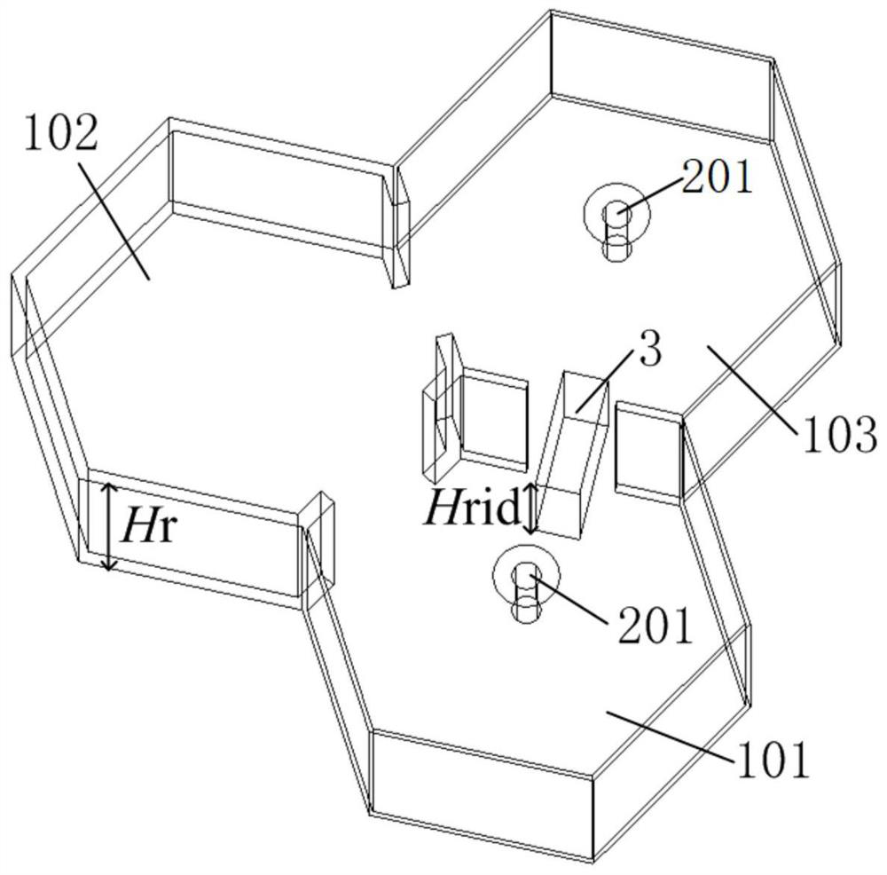
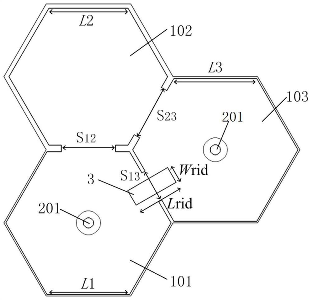
[0030] This embodiment provides a dielectric waveguide filter, such as figure 1 and figure 2 As shown, it includes three interconnected dielectric waveguide resonators and metallized slots 3 .

[0031] Wherein, the metallized groove is straddled on the interface between two adjacent dielectric waveguide resonators; the two adjacent dielectric waveguide resonators are connected through the metallized groove to realize negative coupling. The dielectric waveguide filter body is made of ceramic material. The three dielectric waveguide resonators are a first dielectric waveguide resonator 101 , a second dielectric waveguide resonator 102 and a third dielectric waveguide resonator 103 . The metallization groove 3 is arranged between the first dielectric waveguide resonant cavity 101 and the third dielectric waveguide resonant cavity 103 .

[0032] The metallized groove is arranged across the interface between two adjacent dielectric waveguide resonant cavities and connects the t...


PUM

PropertyMeasurementUnit
lengthaaaaaaaaaa

Abstract

The invention provides a dielectric waveguide filter. The dielectric waveguide filter comprises three interconnected dielectric waveguide resonant cavities and a metallization groove, and the metallization groove is arranged across the interface of two adjacent dielectric waveguide resonant cavities and is connected with the two adjacent dielectric waveguide resonant cavities. A ridge waveguide structure is formed between the metallization groove and the metallization top surface of the dielectric waveguide filter, all the dielectric waveguide resonators work in a TE101 mode during work, and the electric field of the ridge waveguide structure is perpendicular to the metallization top surface of the dielectric waveguide filter. The TE101 mode electric field utilized by the two adjacent dielectric waveguide resonant cavities is also perpendicular to the metallized top surface of the dielectric waveguide filter, so that one resonant cavity in the two adjacent dielectric waveguide resonantcavities can excite the electric field of the ridge waveguide structure, and further excite the electric field of the other resonant cavity; and therefore, negative coupling is generated between thetwo adjacent dielectric waveguide resonant cavities. The selectivity of the ceramic dielectric waveguide filter is improved and the miniaturization of the ceramic dielectric waveguide filter is realized.

Description

technical field [0001] The invention relates to the technical field of communication equipment components, in particular to a dielectric waveguide filter. Background technique [0002] Microwave filters are one of the core components of the RF front-end of communication systems. With the development of communication technology and the increase of communication frequency bands, the demand for microwave filters with low loss and high power capacity is increasing. Ceramic dielectric filters have attracted more and more attention because of their small size, high unloaded quality factor, low loss, large power capacity, and excellent stability. With the development of 5G communication technology, ceramic dielectric filters are expected to become the mainstream technology and have broad market prospects. [0003] Due to the increasing frequency bands of communication systems, it brings challenges to the selectivity and miniaturization of filters. The introduction of cross-negati...

Claims


Application Information

Patent Timeline
Patent Type & Authority Applications(China)
IPC IPC(8): H01P1/20H01P1/208
CPCH01P1/2002H01P1/208
Inventor 郑纬宇张安学舒敏杰陈建忠陈源宝
Owner 人民华智通讯技术有限公司
Learn More