Timber perforating device for mushroom planting
A drilling device and wood technology, applied to fixed drilling machines and other directions, can solve the problems of inability to grasp the drilling accuracy of the drill bit and difficult manual operation
- Summary
- Abstract
- Description
- Claims
- Application Information
AI Technical Summary
Problems solved by technology
Method used
Image
Examples
Embodiment 1
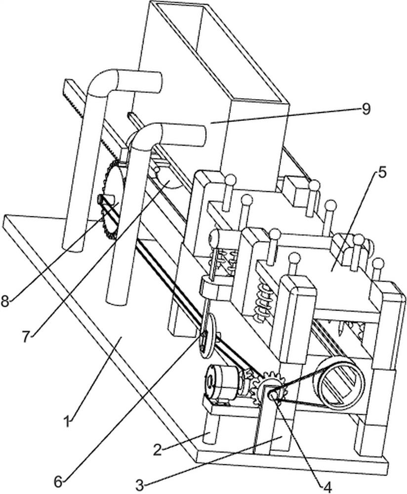
[0075] A device for punching holes in wood for mushroom planting, such as figure 1 As shown, it includes a base 1, a first fixed column 2, a first support seat 3, a rotating mechanism 4 and a punching mechanism 5, the left side of the base 1 is provided with the first fixed column 2, and the right side of the base 1 is evenly provided with Four first support bases 3, the tops of the four first support bases 3 are provided with a rotating mechanism 4, and the rotating mechanism 4 is provided with a punching mechanism 5.
[0076] When people need to punch holes in the wood for planting mushrooms, they can use this punching device for planting mushrooms. First, the user places the wood to be punched on the rotating mechanism 4, and then punches the wood through the punching mechanism 5. hole to achieve the punching effect.
Embodiment 2
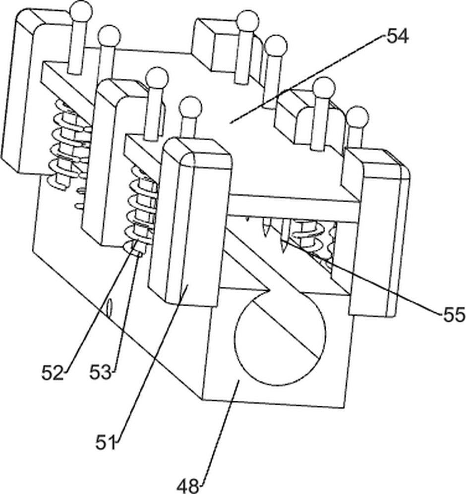
[0078] On the basis of Example 1, such as figure 2 with image 3 As shown, the rotating mechanism 4 includes a second fixed column 41, a first supporting column 410, a motor 42, a first rotating shaft 43, a missing bevel gear 44, a full bevel gear 45, a first transmission assembly 46, a rotating cylinder 47, a fixed frame 48 and the third fixed column 49, the top of the first fixed column 2 is provided with the second fixed column 41, the top of the second fixed column 41 is equipped with a motor 42, the output shaft of the motor 42 is connected with the first rotating shaft 43, the first rotating shaft 43 is provided with missing bevel gear 44, and base 1 upper front side is provided with first support column 410, and first support column 410 top rotation is provided with first transmission assembly 46, and first transmission assembly 46 is provided with full bevel gear 45 , the full bevel gear 45 meshes with the missing bevel gear 44, a third fixed column 49 is arranged be...
Embodiment 3
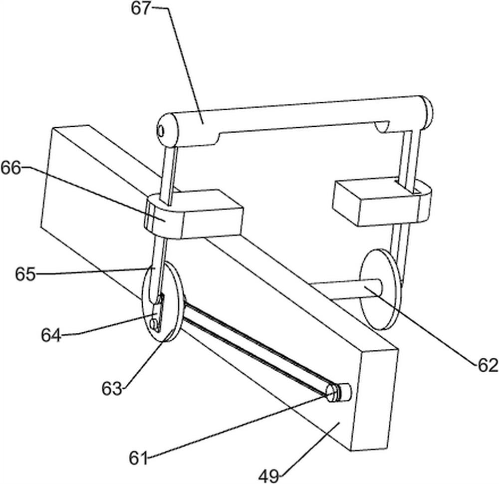
[0083] On the basis of Example 2, such as Figure 4 to Figure 7 As shown, it also includes an up and down reciprocating mechanism 6. The two third fixed columns 49 are provided with an up and down reciprocating mechanism 6. The up and down reciprocating mechanism 6 includes a second transmission assembly 61, a rotating shaft 62, a rotating disc 63, The fifth fixed column 64, the support rod 65, the first slide rail 66 and the sixth fixed column 67, the left part of the front side of the third fixed column 49 is rotatably provided with the second transmission assembly 61, between the two third fixed columns 49 The rotary type is provided with a rotating shaft 62, the other end of the second transmission assembly 61 is connected to the rotating shaft 62, and the rotating disc 63 is provided on the rotating shaft 62, and the left part of the rotating disc 63 on the left is provided with a fifth fixed column 64 , the right part of the rotating disc 63 on the right is provided with...
PUM
 Abstract
Description
Claims
Application Information
 - R&D
- Intellectual Property
- Life Sciences
- Materials
- Tech Scout
- Unparalleled Data Quality
- Higher Quality Content
- 60% Fewer Hallucinations
Browse by: Latest US Patents, China's latest patents, Technical Efficacy Thesaurus, Application Domain, Technology Topic, Popular Technical Reports.
© 2025 PatSnap. All rights reserved.Legal|Privacy policy|Modern Slavery Act Transparency Statement|Sitemap|About US| Contact US: help@patsnap.com


