Device and method for long-distance signal transmission

A long-distance, signal technology, applied in the field of signal transmission, can solve the problems of low, no more than 20Mbps, signal transmission rate decline, signal quality instability, etc., to improve transmission speed, ensure signal transmission quality, and enhance application flexibility. Effect

Active Publication Date: 2021-05-14
WUHAN JINGCE ELECTRONICS GRP CO LTD +1
View PDF10 Cites 0 Cited by
  • Summary
  • Abstract
  • Description
  • Claims
  • Application Information

AI Technical Summary

Problems solved by technology

[0003] When it is transmitted over a long distance, its signal is susceptible to interference, and the signal quality is prone to instability, and the signal transmission rate also decreases, or even cannot work normally.
figure 2 Shown is a schematic diagram of the cross-board interconnection between the QSPI signal source and the QSPI signal receiving end. Experiments show that the longest wiring distance between the QSPI signal source and the QSPI signal receiving end does not exceed 200mm when the cross-board interconnection occurs, and the transmission rate is generally less than 200 mm. Low, no more than 20Mbps, at this time to ensure normal communication; once the wiring distance exceeds 200mm, the signal interference will be large, the transmission rate will also drop seriously, and the normal communication between the QSPI signal source and the QSPI signal receiving end will not be possible.

Method used


Image

  • Device and method for long-distance signal transmission
  • Device and method for long-distance signal transmission
  • Device and method for long-distance signal transmission

Examples


Embodiment Construction

[0046]In order to make the object, technical solution and advantages of the present invention clearer, the present invention will be further described in detail below in conjunction with the accompanying drawings and embodiments. It should be understood that the specific embodiments described here are only used to explain the present invention, not to limit the present invention. In addition, the technical features involved in the various embodiments of the present invention described below can be combined with each other as long as they do not constitute a conflict with each other.

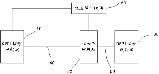
[0047] image 3 It is a schematic diagram of the composition and structure of the device for long-distance signal transmission provided by this embodiment, Figure 4 It is a communication schematic diagram when the device for long-distance signal transmission provided by this embodiment is applied to inter-board communication, see image 3 , Figure 4 , the device includes a QSPI signal contro...


PUM


Abstract

The invention discloses a device and method for long-distance signal transmission. The device includes a QSPI signal control terminal, a signal mutual conversion module and a QSPI signal equipment terminal; the QSPI signal control terminal outputs the QSPI signal in the form of a differential signal, and the QSPI signal Including the differential clock output signal; the signal mutual conversion module receives the differential signal and the QSPI feedback signal returned by the QSPI signal receiving end in the form of a single-ended signal after obtaining the QSPI signal; and realizes the bidirectional conversion of the differential and single-ended signal; the QSPI signal The device end is set at the near end of the signal conversion module, and outputs the QSPI feedback signal in the form of a single-ended signal; the QSPI feedback signal includes a single-ended clock return signal; the single-ended clock return signal is converted into a differential clock return by the signal conversion module The signal is used as the data recovery clock of the QSPI signal control terminal; the present invention performs differential and single-ended conversion on the signal transmission mode, and at the same time designs the returned clock signal at the device end to realize high-speed, high-quality, and long-distance transmission of the signal.

Description

technical field [0001] The invention belongs to the technical field of signal transmission, and more particularly relates to a device and method for long-distance signal transmission. Background technique [0002] At present, QSPI signals are mostly used in the scene of intra-board communication, with short transmission distance and fast transmission speed; figure 1 As shown, the QSPI master control and QSPI device are interconnected on the same board, and the wiring distance is short, which can realize high-speed signal transmission. [0003] When it is transmitted over a long distance, its signal is susceptible to interference, and the signal quality is prone to instability, and the signal transmission rate also decreases, or even cannot work normally. figure 2 Shown is a schematic diagram of the cross-board interconnection between the QSPI signal source and the QSPI signal receiving end. Experiments show that the longest wiring distance between the QSPI signal source an...

Claims


Application Information

Patent Timeline
Patent Type & Authority Patents(China)
IPC IPC(8): G06F13/42G06F15/163
CPCG06F13/4282G06F15/163
Inventor 汪成
Owner WUHAN JINGCE ELECTRONICS GRP CO LTD
Why Eureka
Try Eureka