
Robot joint module driver and control method thereof

A technology of robot joints and control methods, applied in the direction of program control manipulators, manipulators, manufacturing tools, etc., can solve the problems of large stiffness value of the reducer, difficult to obtain the stiffness value of the reducer, low relative torque accuracy, etc., and achieves small size. , The effect of improving joint control performance and torque control performance

Active Publication Date: 2021-03-09
ZHEJIANG LAB
View PDF10 Cites 0 Cited by
  • Summary
  • Abstract
  • Description
  • Claims
  • Application Information

AI Technical Summary

Problems solved by technology

However, the stiffness value of the reducer is not easy to obtain, and the stiffness value of the reducer is generally very large. When the resolution of the encoder is not high, the accuracy of the estimated relative torque is not high, especially when the output torque is small.

Method used


Image

  • Robot joint module driver and control method thereof
  • Robot joint module driver and control method thereof
  • Robot joint module driver and control method thereof

Examples


Embodiment Construction

[0045]The present invention will be described in detail below with reference to the accompanying drawings and preferred embodiments, and the purpose and effect of the present invention will become clearer. It should be understood that the specific embodiments described here are only used to explain the present invention and are not intended to limit the present invention.

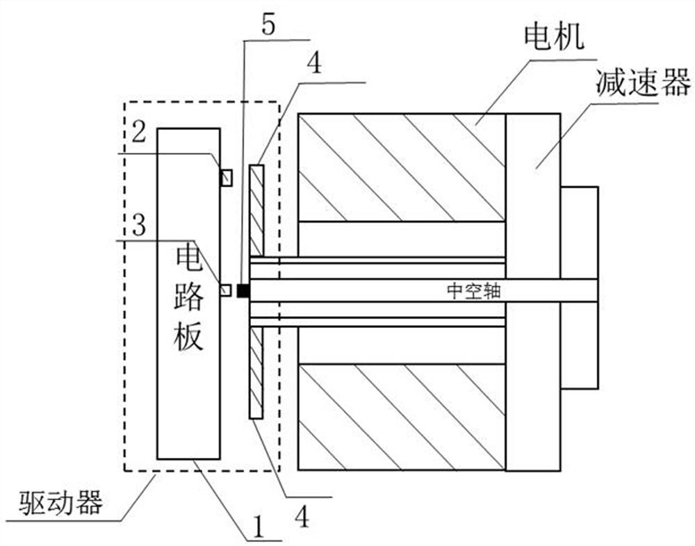
[0046] Such as figure 1 As shown, it is a schematic diagram of the structure of the joint module based on the driver of the present invention. The driver of the present invention includes a driver circuit board 1, a grating code disc 4 and a magnetic block 5, and the grating code disc 4 is installed on the rotating shaft of the motor end of the joint module. , the magnetic block 5 is fixed on the output hollow rotating shaft of the reducer of the joint module; the driver circuit board 1 is fixed on the joint module, which includes a position detection module composed of a photoelectric induction unit 2 and a...


PUM


Abstract

The invention discloses a robot joint module driver and a control method thereof. The driver highly integrates a magnetic induction unit and a light induction unit, and can be used for detecting the positions of a motor end and a joint module output end respectively in cooperation with a grating and a magnetic block, so that the joint control performance is improved, and meanwhile, the small sizeis guaranteed, and the cost is reduced. Meanwhile, according to the control method provided by the invention, closed-loop control is directly carried out on the torque in the innermost loop, and two torque estimation modes of current and a dual encoder are comprehensively used, so that the control capability of the driver on the torque can be improved, and the control performance of the joint module is further improved.

Description

technical field [0001] The invention belongs to the technical fields of motor control and robot control, and in particular relates to a robot joint module driver and a control method thereof. Background technique [0002] The joint module composed of motor, reducer, driver, encoder, etc. is one of the core components of the robot, and is widely used in legged robots, industrial robots and other fields. With the development of technology and the improvement of application requirements, people have higher and higher requirements for the structure size and performance of the joint drive module, which also puts forward higher requirements for the drive of the joint module. [0003] In order to reduce the structural size of the joint drive module, one way is to integrate a magnetic induction chip on the drive and cooperate with the magnetic block to detect the position, such as the MIT Mini Cheetah joint drive module. This way of highly integrating the driver and the encoder can...

Claims


Application Information

Patent Timeline
Patent Type & Authority Applications(China)
IPC IPC(8): B25J9/16B25J17/02B25J13/00
CPCB25J9/1602B25J9/1607B25J17/02B25J13/00
Inventor 华强姚运昌钱坤谢安桓孔令雨张丹
Owner ZHEJIANG LAB
Learn More