
Lead support frame

A support frame and wire technology, used in overhead installation, overhead line/cable equipment, electrical components, etc., can solve problems such as electric shock risk, reduction of wire sag height, safety hazards, etc., to reduce workload and solve electric shock risks. Effect

Active Publication Date: 2021-03-09
GUANGDONG POWER GRID CO LTD +1
View PDF7 Cites 1 Cited by
  • Summary
  • Abstract
  • Description
  • Claims
  • Application Information

AI Technical Summary

Problems solved by technology

[0002] In the process of electric power work, due to the overload of the wires, the weakening of the tension between the poles and other reasons, the wires will be elongated, the sag height of the wires will be reduced, and the distance between the wires and the ground will be insufficient, causing safety hazards, especially when crossing The line of the road, obstructing the normal passage of pedestrians and cars
When dealing with the emergency repair task where the wire is too low, the traditional method is to use wooden sticks or bamboo to support the wire, but this support method is low in safety, and it is easy to be blown down by the wind and hurt people, and the insulation strength cannot be guaranteed. Risk of electric shock

Method used


Image

  • Lead support frame
  • Lead support frame
  • Lead support frame

Examples


Embodiment 1

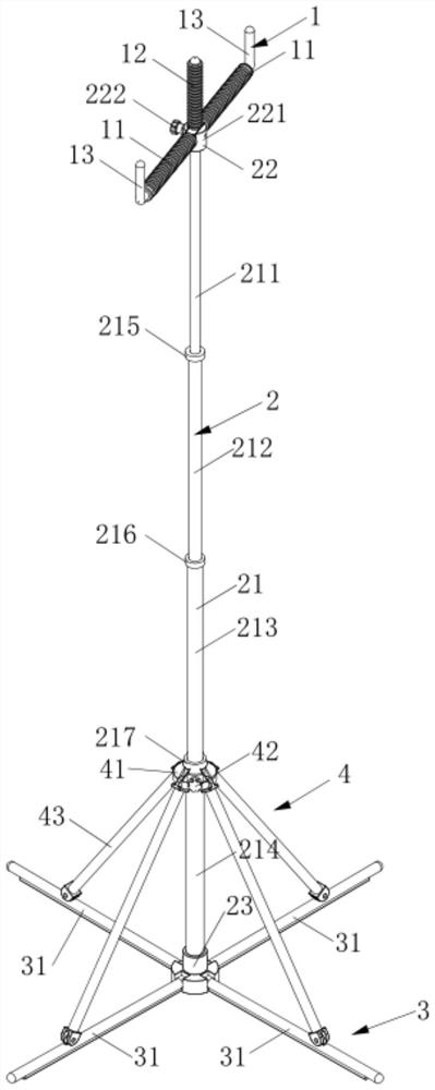
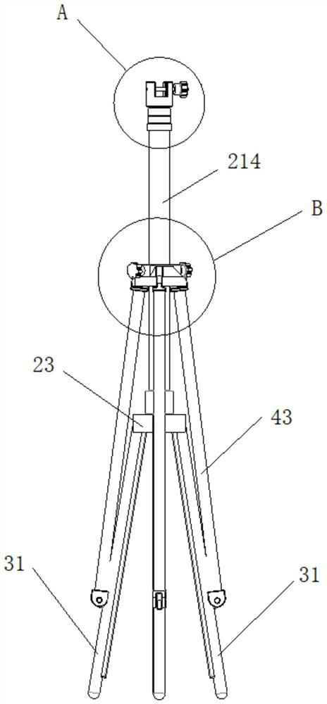
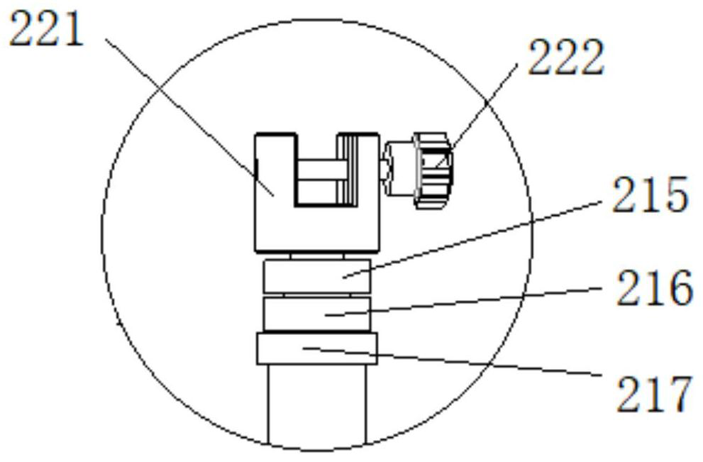
[0037] like Figure 1-Figure 4 As shown, the present invention provides a wire support frame, including a placement frame 1, a lift shaft 2, a chassis 3 and a support mechanism 4, the placement frame 1 is used to support the wire; the length of the lift shaft 2 is adjustable, and the placement frame 1 can be Detachably installed on one end of the lifting shaft 2; the bottom frame 3 is rotatably connected to the other end of the lifting shaft 2; the supporting mechanism 4 is slidably installed on the lifting shaft 2 and connected with the bottom frame 3, and the supporting mechanism 4 slides relative to the lifting shaft 2 , can drive the bottom frame 3 to expand or close. When the bottom frame 3 is unfolded, it is perpendicular to the lifting shaft 2 and can support the lifting shaft 2. When the bottom frame 3 is closed, it is attached to the lifting shaft 2.

[0038] In this embodiment, when using the wire support frame, the placement frame 1 is first installed on the lifting...

Embodiment 2

[0052] This embodiment provides a wire support frame, which is further improved on the basis of Embodiment 1 to further enhance the stability of the wire support frame.

[0053] More specifically, an anti-slip member is provided on the side of the pole 31 away from the supporting mechanism 4 . In this embodiment, the anti-slip member may be rubber to enhance the friction between the pole 31 and the ground.

[0054] More specifically, the bottom of the connection base 23 is provided with spikes, which can be inserted into the ground, so that the wire support frame is not easy to fall.


PUM


Abstract

The invention belongs to the technical field of power line application, and discloses a wire support frame. The support frame comprises a placement frame, a lifting shaft, a bottom frame and a supportmechanism; the placement frame is used for supporting wires; the length of the lifting shaft is adjustable, and the placing frame is detachably installed at one end of the lifting shaft; the underframe is rotationally connected to the other end of the lifting shaft; the supporting mechanism is installed on the lifting shaft in a sliding mode and connected with the bottom frame, when the supporting mechanism slides relative to the lifting shaft, the bottom frame can be driven to be unfolded or folded, and when the bottom frame is unfolded, the supporting mechanism is perpendicular to the lifting shaft and can support the lifting shaft, and when the bottom frame is closed, the supporting mechanism abuts against the lifting shaft. The wire supporting frame can be applied to repair operationof an excessively-low power grid wire, the electric shock risk caused by the excessively-low wire is avoided, the wire supporting frame can be rapidly assembled in use and can be rapidly disassembled,assembled and stored after the repair operation is finished, and the workload of a basic-level repair rush-to-work period can be effectively reduced.

Description

technical field [0001] The invention relates to the technical field of power line applications, in particular to a wire support frame. Background technique [0002] In the process of electric power work, due to the overload of the wires, the weakening of the tension between the poles and other reasons, the wires will be elongated, the sag height of the wires will be reduced, and the distance between the wires and the ground will be insufficient, causing safety hazards, especially when crossing The line of the road hinders the normal passage of pedestrians and cars. When dealing with the emergency repair task where the wire is too low, the traditional method is to use wooden sticks or bamboo to support the wire, but this support method is low in safety, and it is easy to be blown down by the wind and hurt people, and the insulation strength cannot be guaranteed. There is a risk of electric shock. Contents of the invention [0003] The purpose of the present invention is t...

Claims


Application Information

Patent Timeline
Patent Type & Authority Applications(China)
IPC IPC(8): H02G1/04H02G7/00
CPCH02G1/04H02G7/00
Inventor 邹裕青周梓乐张盛芳骆凯骆晨芳张碧其钟毅殷栢辉黄海清陈威何祥平甘运斌杨素萍骆灯基徐裕龙刘小媚
Owner GUANGDONG POWER GRID CO LTD
Learn More