Cloud computing multistage scheduling method and system and storage medium

A scheduling method and cloud computing technology, applied in the field of cloud computing, can solve the problem of high average completion time of Coflow

Pending Publication Date: 2021-03-09
STATE GRID ELECTRIC POWER RES INST +3
View PDF0 Cites 0 Cited by
  • Summary
  • Abstract
  • Description
  • Claims
  • Application Information

AI Technical Summary

Problems solved by technology

[0004] Aiming at the problem that the average completion time of Coflow still exists in the current multi-level scheduling optimization technology, the present invention provides a cloud computing multi-level scheduling method and system

Method used


Image

  • Cloud computing multistage scheduling method and system and storage medium
  • Cloud computing multistage scheduling method and system and storage medium
  • Cloud computing multistage scheduling method and system and storage medium

Examples


Embodiment 1

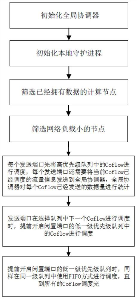
[0049] Embodiment 1. A cloud computing multi-level scheduling method, comprising the following steps:

[0050] Select the receiving node and notify the sending node of Coflow, so that the sending node will send the scheduled Coflow traffic to the selected receiving node;

[0051] Receive the sent data flow size information of each Coflow sent by the sending node, determine the priority of different Coflows according to the received information, and send the priority of the Coflow to the sending node, so that the sending node Coflow is scheduled in the local multi-level queue according to the priority of the above Coflow.

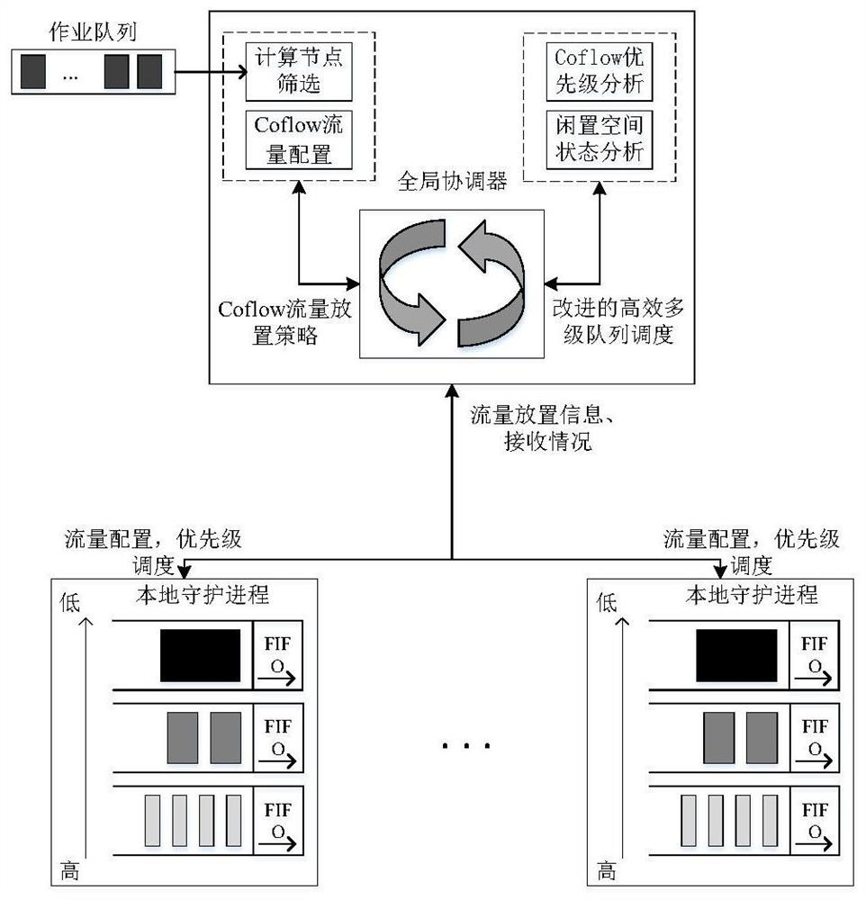
[0052] The execution subject of the method in this embodiment is independent of the sending node and the receiving node, and can be set in, for example, a global coordinator or an integrated coordinator.

Embodiment 2

[0053] Embodiment two, on the basis of implementing one, the method for selecting the receiving node in this embodiment is: monitor the job that produces Coflow and utilize the Coflow flow placement strategy to select the receiving node to be placed for Coflow flow, and the Coflow flow placement strategy includes preliminary Screen the computing nodes that already have data, and screen the nodes with low network load among the computing nodes that are initially screened out.

[0054] Preliminary screening of computing nodes that already have data is represented by formula (3). in, The representation of C n Whether the i-th data stream in can select node j as a potential target node, if the value is 1, it means yes, otherwise it is 0. all All nodes will be selected as the set of candidate computing nodes for task i.

[0055]

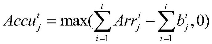
[0056] Among the computing nodes initially screened out, the nodes with small network load are screened again. exist In the case of , it can ...

Embodiment 3

[0069] Embodiment three, a kind of cloud computing multi-level scheduling method, comprises the following steps: A kind of cloud computing multi-level scheduling method, is characterized in that, comprises the following steps:

[0070] Obtain the receiving node selected by the global coordinator, and send the scheduled Coflow traffic to the selected receiving node;

[0071] Send the data flow size information sent by each Coflow to the global coordinator, so that the global coordinator determines the priorities of different Coflows according to the received information and returns the priorities of the different Coflows;

[0072] Scheduling the Coflow in the local multi-level queue according to the received priority of the Coflow.

[0073] The method provided in this embodiment is deployed on the sending node, in which a global coordinator is added for convenience of description, which cannot be understood as a limitation on the execution subject, and can be implemented by oth...


PUM


Abstract

The invention provides a cloud computing multistage scheduling method which comprises the following steps: selecting a receiving node and notifying a sending node of Coflow, so that the sending node sends the flow in the scheduled Coflow to the selected receiving node; and receiving data flow size information sent by each Coflow and sent by the sending node, determining priorities of different Coflows according to the received information, and sending the priorities of the Coflows to the sending node, so that the sending node schedules the Coflows in a local multi-level queue according to thereceived priorities of the Coflows. By optimizing cloud computing multi-level scheduling, the communication efficiency of the internal network of the cloud environment can be improved, and the computing value of cloud computing can be better exerted.

Description

technical field [0001] The invention relates to a cloud computing multi-level scheduling method, system and storage medium, belonging to the technical field of cloud computing. Background technique [0002] At present, in order to improve resource utilization and the efficiency of large-scale task processing, a large number of redundant idle computers are often connected through cluster technology to form a cloud data center. In cloud data centers, distributed parallel computing frameworks such as MapReduce and Spark are usually used to process large-scale data. Due to the adoption of a distributed computing framework, a job is often divided into multiple subtasks and handed over to multiple computers in the data center for completion. When subtasks are distributed and subtask results are merged, a large number of intermediate tasks will be generated. communication data flow. If one of the data streams fails to complete in time, the subsequent subtasks that depend on the r...

Claims


Application Information

Patent Timeline
IPC IPC(8): H04L12/869H04L12/865H04L12/851H04L47/6275
CPCH04L47/58H04L47/6275H04L47/2433H04L47/2441
Inventor 刘军刘赛张磊张敏杰晁凯杨勰宋凯吴垠胡楠杨清松杨文清胡游君邱玉祥高雪叶莹卢仕达陈琰张露维陈晓露顾荣斌
Owner STATE GRID ELECTRIC POWER RES INST
Why Eureka
Try Eureka