
File structure with good balance effect and pressing function

A filing and balancing technology, which is used in manufacturing tools, filing/filing devices, filing/filing devices, etc., can solve problems such as time-consuming and labor-intensive, and achieve the effect of reducing operation difficulty, good balancing effect, and improving work accuracy.

Inactive Publication Date: 2021-03-12
刘绍警
View PDF0 Cites 0 Cited by
  • Summary
  • Abstract
  • Description
  • Claims
  • Application Information

AI Technical Summary

Problems solved by technology

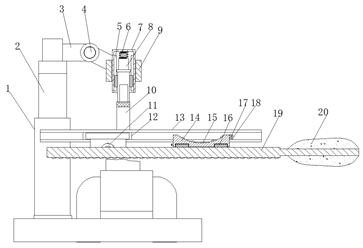
[0004] In order to overcome the time-consuming and labor-intensive problem in the prior art when frustrating a rough and irregular workpiece surface, the present invention provides a file structure with a good balance effect and a pressing function

Method used


Image

  • File structure with good balance effect and pressing function
  • File structure with good balance effect and pressing function
  • File structure with good balance effect and pressing function

Examples


Embodiment 1

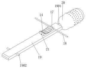
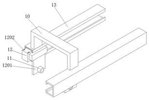
[0028] refer to Figure 1-4 , a file structure with a good balance effect and a press-down function, including a file body 19 and a support frame 1 fixed on a hydraulic clamp fixing platform, an extension rod 2 is arranged on the top of the support frame 1, and the top of the extension rod 2 The arm bar 3 is fixed, the end of the arm bar 3 is provided with a fixed frame 9, the middle of the fixed frame 9 is clamped with a fixed bucket 7 with the opening downward, and the bottom opening of the fixed bucket 7 is slidably connected with an electric push rod 8 The upper and lower ends of the electric push rod 8 are respectively fixed with a compression spring 6 and a bow frame 10, and the bottom end of the bow frame 10 is fixed with two C-shaped steel slide rails 13 with opposite openings and parallel to each other, and the two C-shaped steel slide rails 13 T-shaped sliders 12 are slidably connected in the chute, bearing fixing plates 1201 are fixed on opposite sides of the two T-...

Embodiment 2

[0038] refer to figure 1 and Figure 5 , a file structure with a good balance effect and a pressing function. Compared with Embodiment 1, this embodiment also includes that the span of the bow frame 10 is greater than the distance between two C-shaped steel slide rails 13, and the bow frame 10 Both legs are provided with threaded holes close to the back of the C-shaped steel slide rail 13 and the back of the C-shaped steel slide rail 13. Adjusting bolts 22 are screwed in the threaded holes, and the two C-shaped steel slide rails 13 of the bow frame 10 are fixed by the adjusting bolts 22. together, and the inclination angle of the C-shaped steel slide rail 13 can be changed according to the angle of the workpiece's foiling plane, so that the user can foil an inclined plane.


PUM


Abstract

The invention belongs to the technical field of bench work equipment, particularly relates to a file structure with a good balance effect and a downward pressing function, and provides the following scheme for solving the problem that in the prior art, time and labor are wasted when the surface of a rough irregular workpiece is filed. According to the scheme, the file structure comprises a file body and a supporting frame fixed to a hydraulic clamp fixing table; an extension rod is arranged at the top end of the supporting frame; an arm rod is fixed to the top of the extension rod; a fixing frame is arranged at the end of the arm rod; a fixing barrel with a downward opening is clamped in the middle of the fixing frame; an electric push rod is connected to the opening in the bottom end of the fixing barrel in a sliding manner; and a compression spring and an arch-shaped frame are fixed to the upper end and the lower end of the electric push rod correspondingly. When the file structure is used, downward pressure can be generated on the front half portion of a file when a workpiece is filed, at the moment, a user only needs to lift the tail portion of a file body to be kept horizontaland then pushes the file body back and forth along a C-shaped steel sliding rail, and physical power is greatly saved.

Description

technical field [0001] The invention relates to the technical field of fitter equipment, in particular to a file structure with a good balance effect and a pressing function. Background technique [0002] A file is a tool for filing metal, wood and other materials. A file generally includes a file body and a file handle, and a filing pattern is provided on the file body. Existing files only have a single file body. Sometimes when encountering some inclined rough planes that need to be filed to a horizontal state and where the CNC machine tool has a special structure, the operation cannot be completed. At this time, clamps are needed to cooperate. Perform manual trimming. [0003] However, for this kind of device that requires high precision to be frustrated only by handwork, the technical requirements of the fitter master are very high. Although there is no shortage of such high-precision talents in the industry, the work of frustrating is a waste of time. Physical and en...

Claims


Application Information

Patent Timeline
Patent Type & Authority Applications(China)
IPC IPC(8): B23D69/02B23D69/00B23D67/12
CPCB23D67/12B23D69/00B23D69/02
Inventor 刘绍警
Owner 刘绍警
Learn More