

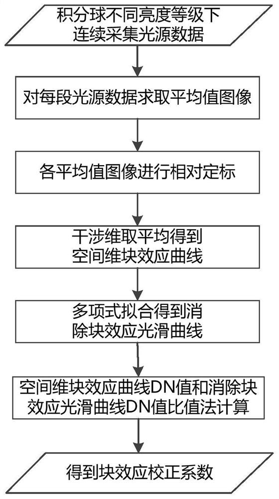
A correction method for detector block effect of interferometric imaging spectrometer
A technology of interferometric imaging and correction method, applied in interferometric spectroscopy, spectrometry/spectrophotometry/monochromator, instruments, etc., which can solve the problem of non-uniformity correction of interferometric imaging spectrometer images and inconsistent detector response. , ignoring the dynamic changes of the detector block effect, etc., to achieve the effect of removing adverse effects, improving stability and accuracy, and good stability and accuracy
- Summary
- Abstract
- Description
- Claims
- Application Information
AI Technical Summary
Problems solved by technology
Method used
Image

Examples
Embodiment Construction
[0049] The technical solutions of the present invention will be clearly and completely described below in conjunction with the embodiments of the present invention and the accompanying drawings. Apparently, the described embodiments do not limit the present invention.
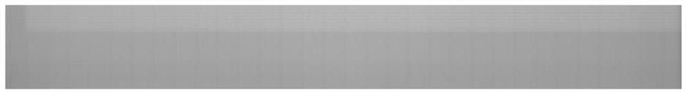
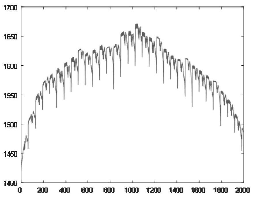
[0050]The sampling of the interference imaging spectrometer varies with temperature (time), resulting in block effects in the block output image, which makes the image uniformity poor. Such as figure 2 It is a quick view of the integrating sphere data collected by the interferometric imaging spectrometer in 1 second. After dark current removal, bad pixel correction and detector response correction, it can be seen that the image still has obvious block effect, and its spatial dimension difference curve (using the interferometric Dimensional average representation) such as image 3 As shown, the downward concave portion of the curve represents the edge of the block.
[0051] In the method for correcting the bl...
PUM
 Abstract
Description
Claims
Application Information