Backlight Modules and Display Devices

A technology for backlight modules and light source components, applied in the directions of light guides, optics, optical components, etc., can solve the problems of uneven display and uneven light, and achieve the effect of reducing the brightness of the light output, improving the bright band, and weakening the effect of concentrating light.

Active Publication Date: 2022-08-09
XIAMEN TIANMA MICRO ELECTRONICS
View PDF8 Cites 0 Cited by
  • Summary
  • Abstract
  • Description
  • Claims
  • Application Information

AI Technical Summary

Problems solved by technology

[0002] With the development of display technology, in the design of current display devices such as mobile phones, the requirements for screen-to-body ratio are getting higher and higher, that is, the ratio of the area of ​​the display area of ​​the display device to the area of ​​the non-display area is getting larger and larger. The display device usually has a hole in the backlight module to place the camera. This design of the hole makes the frame of the display device narrower. In the part facing away from the light source, since the light source cannot be directly irradiated, dark bands will appear in a certain area, resulting in uneven light and uneven display.

Method used


Image

  • Backlight Modules and Display Devices
  • Backlight Modules and Display Devices
  • Backlight Modules and Display Devices

Examples


Embodiment Construction

[0029] Various exemplary embodiments of the present invention will now be described in detail with reference to the accompanying drawings. It should be noted that the relative arrangement of the components and steps, the numerical expressions and numerical values ​​set forth in these embodiments do not limit the scope of the invention unless specifically stated otherwise.

[0030] The following description of at least one exemplary embodiment is merely illustrative in nature and is in no way intended to limit the invention, its application, or uses.

[0031] Techniques, methods, and devices known to those of ordinary skill in the relevant art may not be discussed in detail, but where appropriate, such techniques, methods, and devices should be considered part of the specification.

[0032] In all examples shown and discussed herein, any specific values ​​should be construed as illustrative only and not limiting. Accordingly, other instances of the exemplary embodiment may hav...


PUM


Abstract

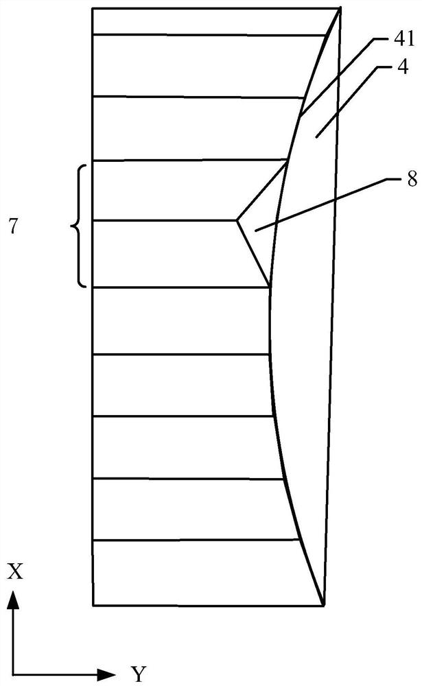
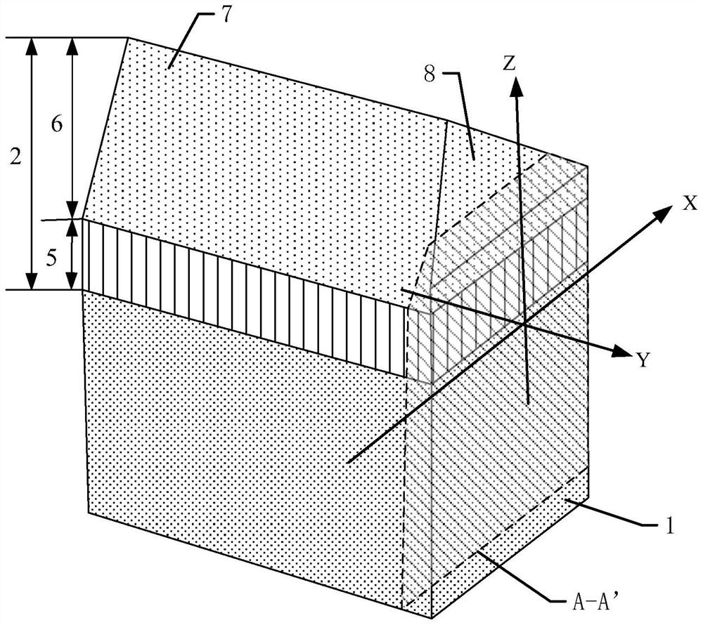
The invention discloses a backlight module and a display device. The backlight module comprises: a light source assembly located on at least one side of a light guide plate with a light exit surface of the light source assembly facing the light incident surface of the light guide plate, and a light enhancement film located on the light exit surface of the light guide plate One side of the surface; the backlight module includes a through hole, the through hole penetrates the light guide plate and the light enhancement film, and the hole wall of the through hole includes the outer hole wall close to the light source assembly; the light enhancement film includes a substrate layer and a prism layer, and the prism layer is located on the substrate The side of the layer away from the light guide plate, the prism layer includes a plurality of prism strips arranged in parallel, at least one prism strip includes a first end face facing the outer hole wall, the first end face faces the side away from the base material layer, at least one first end face There is a first included angle α with the plane where the light guide plate is located, and α is an acute angle. The acute angle between the first end face and the plane of the light guide plate changes the light path passing through the first end face of the prism strip, destroys the light concentrating effect of the prism strip at the first end face, and improves the problem that bright bands are easily generated at the through holes of the backlight module.

Description

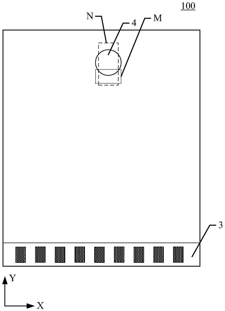
technical field [0001] The present invention relates to the field of display technology, and more particularly, to a backlight module and a display device. Background technique [0002] With the development of display technology, in the design of current display devices such as mobile phones, the requirements for screen ratio are getting higher and higher, that is, the ratio of the area of ​​​​the display area of ​​the display device to the area of ​​the non-display area is increasing. The display device usually has a hole in the backlight module to place the camera. This hole design makes the frame of the display device narrow, but in the part facing the light source, due to the direct illumination of the light source, it will inevitably appear bright in a certain area. In the part facing away from the light source, since the light source cannot be directly illuminated, a dark band will appear in a certain area, resulting in uneven light and uneven display. SUMMARY OF THE...

Claims


Application Information

Patent Timeline
Patent Type & Authority Patents(China)
IPC IPC(8): G02B6/00G02B5/02G02F1/13357
CPCG02B6/0035G02B5/021G02F1/133615
Inventor 马雄斌柯耀作郭凡李蓬勃陈燕青
Owner XIAMEN TIANMA MICRO ELECTRONICS
Why Eureka
Try Eureka