A multi-functional orientation-adjustable ink printing device

A azimuth adjustment and ink printing technology, applied in printing, printing presses, rotary printing presses, etc., can solve the problems of poor printing effect and easy to change the printed matter, and achieve the effect of facilitating printing work and preventing movement.

Active Publication Date: 2022-06-28
临沂市大阳印刷有限公司
View PDF14 Cites 0 Cited by
  • Summary
  • Abstract
  • Description
  • Claims
  • Application Information

AI Technical Summary

Problems solved by technology

[0005] In order to overcome the current disadvantages of needing to adjust the position of the printed matter when changing the printing position, easily changing the state of the printed matter, and making the printing effect poor, the purpose of the present invention is to provide a multifunctional azimuth-adjustable ink that can adjust the position of the printing parts printing device

Method used


Image

  • A multi-functional orientation-adjustable ink printing device
  • A multi-functional orientation-adjustable ink printing device
  • A multi-functional orientation-adjustable ink printing device

Examples


Embodiment 1

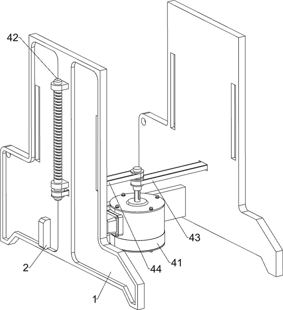
[0028] A multifunctional azimuth-adjustable ink printing device, such as figure 1 , figure 2 , image 3 and Figure 4 As shown, it includes a bracket 1, a support plate 2, a guide block 3, a drive assembly 4, a placement assembly 5 and a printing assembly 6. The lower part of the bracket 1 is connected with a support plate 2, and the left and right sides of the rear of the bracket 1 are fixed by bolts. The guide block 3 is provided with a driving component 4 between the bracket 1 and the support plate 2 , a placing component 5 is arranged between the bracket 1 and the driving component 4 , and a printing component 6 is arranged on the bracket 1 .

[0029] When printing is required, first place the object to be printed on the placement assembly 5, and apply ink to some parts of the printing assembly 6, and then the drive assembly 4 can be controlled to start working, and the drive assembly 4 will drive the placement assembly 5 to move up, so that the The printing assembly 6...

Embodiment 2

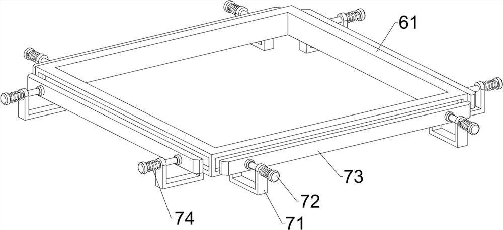
[0037] On the basis of Example 1, as figure 1 , Figure 5 and Image 6 As shown, a clamping assembly 7 is also included. The clamping assembly 7 includes a guide plate 71, a sliding rod 72, a clamping plate 73 and a second spring 74. The outer side of the square frame 61 is symmetrically provided with a guide plate 71, and the upper part of the guide plate 71 is slidably arranged. There is a sliding rod 72 , a clamping plate 73 is connected between the sliding rods 72 on the same side, the clamping plate 73 cooperates with the supporting plate 63 , and a second spring 74 is connected between the sliding rod 72 and the adjacent guide plate 71 .

[0038]When the guide plate 64 needs to be moved, it is necessary to first pull the splint 73 away from the square frame 61 . The movement of the splint 73 will also drive the slide bar 72 to move, and the second spring 74 is stretched. The guide plate 64 can be moved. When the guide plate 64 is moved to a suitable position, the pulli...

Embodiment 3

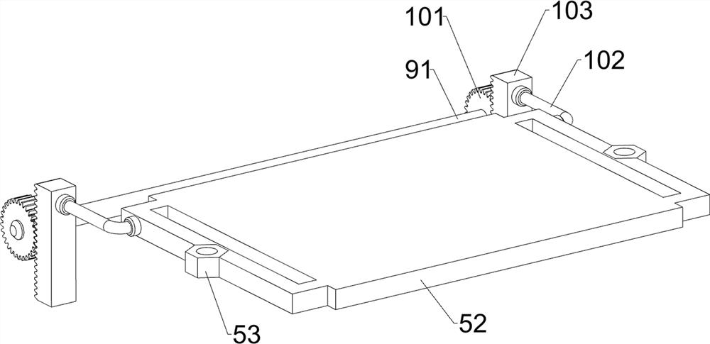
[0042] On the basis of Example 2, as figure 1 , Figure 7 and Figure 8 As shown, it also includes a smearing assembly 9. The smearing assembly 9 includes a rotating rod 91, a guide rail 92, a U-shaped rod 93, a long rod 94, a liquid storage frame 95, a sponge cylinder 96 and a collection frame 97. The rear side of the bracket 1 rotates There is a rotating rod 91, the left and right sides of the rotating rod 91 are connected with guide rails 92, a U-shaped rod 93 is slidably arranged between the guide blocks 3, and a long rod 94 is connected to the rear of the U-shaped rod 93, and the long rod 94 and the guide rails 92 sliding fit, a liquid storage frame 95 is connected between the guide blocks 3, a sponge cylinder 96 is rotatably provided on the front side of the U-shaped rod 93, and a collection frame 97 is connected to the front side of the U-shaped rod 93.

[0043] When the printing mold 67 starts to print, ink can be added to the liquid storage frame 95 first, and then ...


PUM


Abstract

The invention relates to a printing device, in particular to a multi-functional orientation-adjustable ink printing device. The object of the present invention is to provide a multi-functional azimuth-adjustable ink printing device that can adjust the position of printing components. A multi-functional azimuth-adjustable ink printing device includes: a bracket; a support plate installed on the bracket; a guide block installed on both sides of the bracket; a driving component installed between the bracket and the support plate; a placement component installed on the Between the bracket and the drive assembly; the printed assembly, mounted on the bracket. In the present invention, the printed object is placed on the placing assembly, and the driving assembly drives the placing assembly to move upward, so that the printing assembly can print the printed object. After the printing is completed, the driving assembly can drive the placing assembly to reset. Before printing, it can also Move the position of the printing mold so that the device can print on different positions.

Description

technical field [0001] The invention relates to a printing device, in particular to an ink printing device with multifunctional orientation adjustment. Background technique [0002] Printing is to transfer the ink to the surface of the printed object through processes such as plate making, ink application, pressure, etc., so as to carry out the graphic communication work through the printed object. When businesses promote paper objects, they often use the printing process. [0003] When the current printing device is performing printing work, it can only perform printing work on one position, and cannot perform printing work on other positions. Therefore, the printing position is changed, and when the position of the printed object is adjusted, the state of the printed object is easily changed, resulting in poor printing effect. [0004] Therefore, there is a need to design a multifunctional azimuth-adjustable ink printing device that can adjust the position of the printing...

Claims


Application Information

Patent Timeline
Patent Type & Authority Patents(China)
IPC IPC(8): B41F17/00
CPCB41F17/00
Inventor 郭根平
Owner 临沂市大阳印刷有限公司
Why Eureka
Try Eureka