Take-up mechanism for power installation
A wire take-up mechanism and installation technology, which is applied in the direction of transportation and packaging, delivery of filamentous materials, thin material processing, etc., to achieve the effect of convenient repair and prevention of over-tightening or over-loosening
- Summary
- Abstract
- Description
- Claims
- Application Information
AI Technical Summary
Problems solved by technology
Method used
Image

Examples
specific Embodiment approach 1
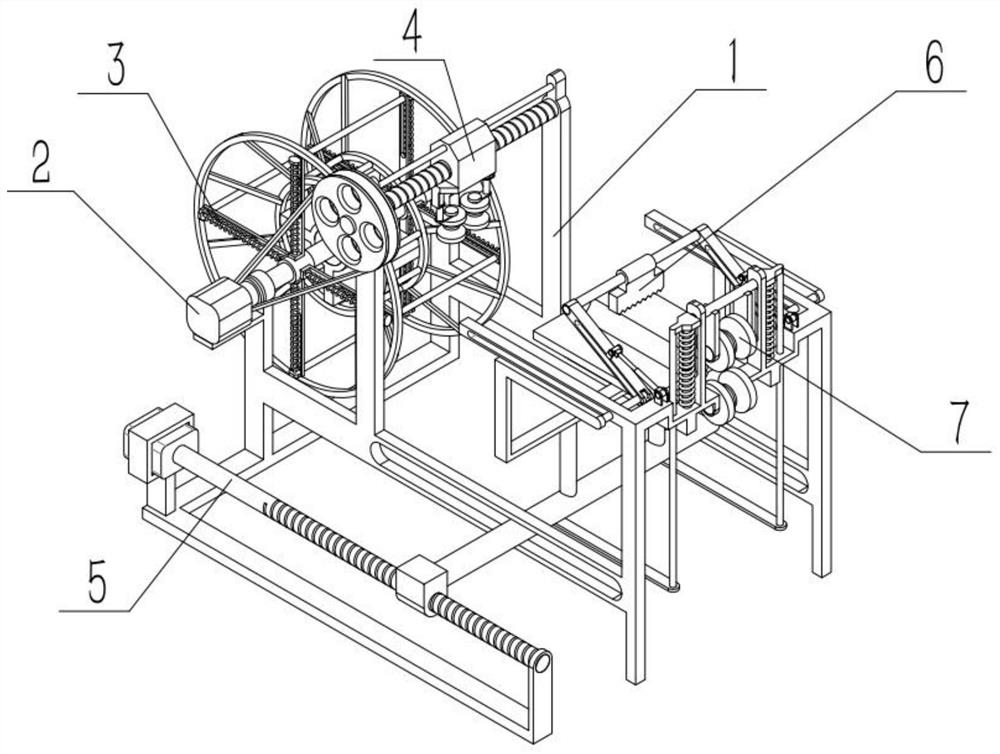
[0031] Such as Figure 1-9 As shown, a wire take-up mechanism for electric installation includes a wire take-up frame 1, a wire take-up mechanism 2, a telescopic mechanism 3, a traverse mechanism 4, a power mechanism 5, a clamping mechanism 6 and a flow guide mechanism 7. Mechanism 2 is connected to the left end of the take-up frame 1, the telescopic mechanism 3 is connected to the middle of the take-up mechanism 2, the traverse mechanism 4 is connected to the take-up frame 1, the power mechanism 5 is connected to the middle of the take-up frame 1, and the clamping mechanism 6 is connected to the front end of the power mechanism 5, and the flow guiding mechanism 7 is connected to the right end of the take-up frame 1. The invention can prevent some aging wires from breaking while taking up the wires. At the same time, if the wires are aging and broken, the broken aging wires can be grasped in time to prevent falling off and the wires can touch the staff to avoid electric shock ...
specific Embodiment approach 2
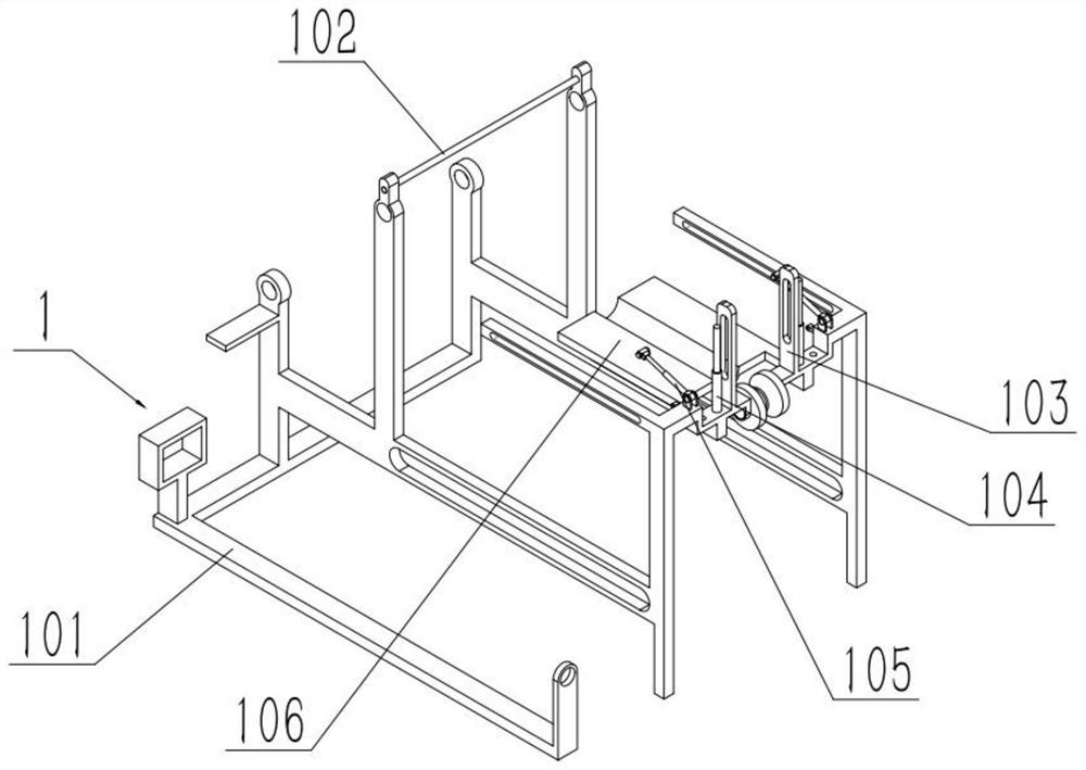
[0033] Such as Figure 1-9 As shown, a wire take-up mechanism for electric installation, the wire take-up frame 1 includes a frame 101, a convex seat 103, a first telescopic rod 104 and a second telescopic rod 105, and the front and rear ends of the upper right side of the frame 101 are fixed respectively One convex seat 103, two first telescopic rods 104 are provided with, the fixed ends of two first telescopic rods 104 are fixedly connected to the front and rear ends of the upper right side of frame 101 respectively, the second telescopic rod 105 is provided with two, two The fixed ends of the second telescopic rod 105 are respectively rotatably connected to the front and rear ends of the upper end on the right side of the frame 101. The frame 101 has a stable structure and is convenient for use and storage, and there are two wheels between the lower ends of the two bosses 103, which are convenient for wire transmission and subsequent wire take-up.
specific Embodiment approach 3
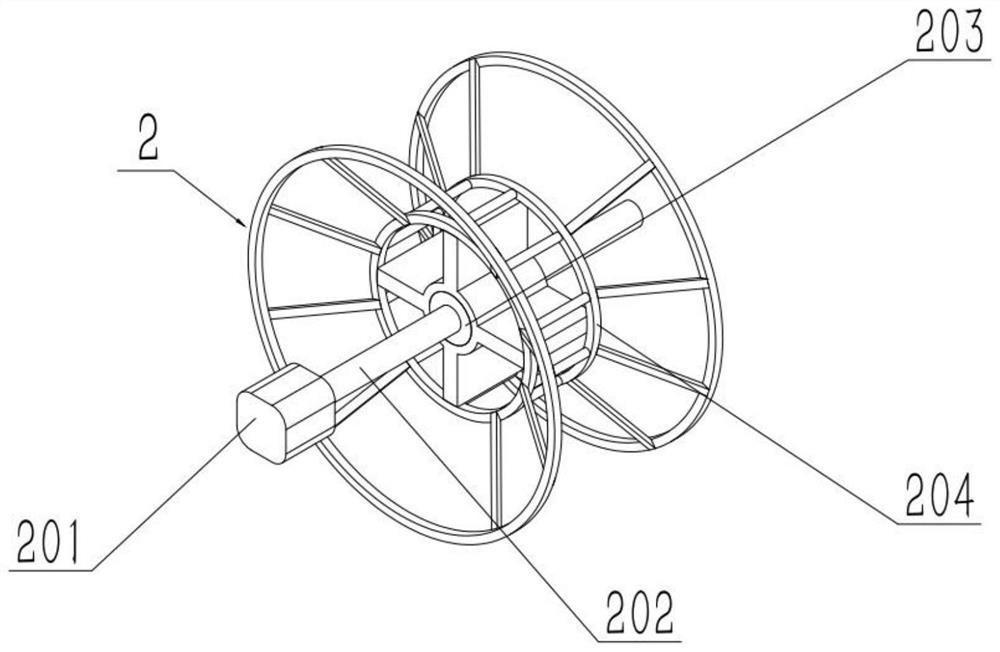
[0035] Such as Figure 1-9As shown, a take-up mechanism for electric installation, the take-up mechanism 2 includes a take-up motor 201, a take-up rod 202, a drive ring 203 and a winding ring 204, the output shaft of the take-up motor 201 is connected to the The take-up rod 202 is fixedly connected, and the drive ring 203 is fixedly connected to the middle part of the take-up rod 202. The two ends are respectively rotatably connected to the front and rear ends of the left end of the frame 101 . When carrying out take-up, drive the take-up motor 201 to drive the take-up rod 202 and the driving ring 203 to rotate, this time can drive the winding ring 204 to rotate, and the winding ring 204 is a circular ring extending outward on both sides. The staff can pile up the wires to both sides while taking up the wires, thereby increasing the collection efficiency and quantity of the wires. When taking up the wires, the wire ends are wound in the middle of the wire winding ring 204 by ...
PUM
 Abstract
Description
Claims
Application Information
 - Generate Ideas
- Intellectual Property
- Life Sciences
- Materials
- Tech Scout
- Unparalleled Data Quality
- Higher Quality Content
- 60% Fewer Hallucinations
Browse by: Latest US Patents, China's latest patents, Technical Efficacy Thesaurus, Application Domain, Technology Topic, Popular Technical Reports.
© 2025 PatSnap. All rights reserved.Legal|Privacy policy|Modern Slavery Act Transparency Statement|Sitemap|About US| Contact US: help@patsnap.com