Oil groove sealing structure

A sealing structure and oil groove technology, which is applied in the direction of engine seals, shafts and bearings, bearing components, etc., can solve the problems of poor sealing reliability, difficult adjustment of sealing gap between sealing teeth and rotating parts, unfavorable sealing performance, etc., and achieve long-lasting The effect of sealing, preventing loosening, and ensuring the reliability of use

Pending Publication Date: 2021-03-19
DONGFANG ELECTRIC MACHINERY
View PDF15 Cites 0 Cited by
  • Summary
  • Abstract
  • Description
  • Claims
  • Application Information

AI Technical Summary

Problems solved by technology

However, the sealing gap between the sealing teeth and the rotating parts is still difficult to adjust, which is not conducive to maintaining a long-lasting sealing performance, and the sealing reliability is not good

Method used


Image

  • Oil groove sealing structure
  • Oil groove sealing structure
  • Oil groove sealing structure

Examples


Embodiment 1

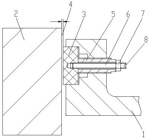
[0028] see figure 1 , an oil groove sealing structure, including a sealing cover 1 and a sealing tooth 3 adapted to a rotating part 2, a sealing gap 4 is formed between the sealing tooth 3 and the rotating part 2, and the sealing tooth 3 and the sealing cover 1 are in clearance fit, said The sealing cover 1 is provided with an adjustment member 5, the adjustment member 5 is connected with a screw 6, the screw 6 is covered with a nut 7, the end of the screw 6 is provided with a notch 8, and the sealing tooth 3 is connected with the adjustment Part 5 is tightly connected by screw rod 6 .

[0029] This embodiment is the most basic implementation. A sealing gap 4 is formed between the sealing tooth 3 and the rotating part 2. The sealing tooth 3 and the sealing cover 1 are in clearance fit. The sealing cover 1 is provided with an adjustment member 5, which penetrates Connected with a screw 6, the screw 6 is covered with a nut 7, the end of the screw 6 has a notch 8, the sealing to...

Embodiment 2

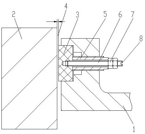
[0031] see figure 2 , an oil groove sealing structure, including a sealing cover 1 and a sealing tooth 3 adapted to a rotating part 2, a sealing gap 4 is formed between the sealing tooth 3 and the rotating part 2, and the sealing tooth 3 and the sealing cover 1 are in clearance fit, said The sealing cover 1 is provided with an adjustment member 5, the adjustment member 5 is connected with a screw 6, the screw 6 is covered with a nut 7, the end of the screw 6 is provided with a notch 8, and the sealing tooth 3 is connected with the adjustment Part 5 is tightly connected by screw rod 6 .

[0032] There are two nuts 7 , and the two nuts 7 are arranged side by side on the screw rod 6 .

[0033] This embodiment is a preferred implementation mode. There are two nuts 7, and the two nuts 7 are arranged side by side on the screw rod 6. By adopting the double nut 7 structure, the sealing teeth 3 and the adjustment member 5 can be firmly connected together to ensure Use reliability. ...

Embodiment 3

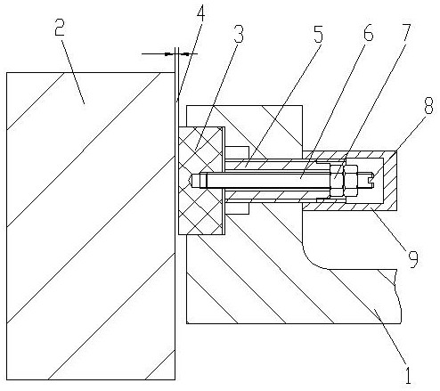
[0035] see image 3 , an oil groove sealing structure, including a sealing cover 1 and a sealing tooth 3 adapted to a rotating part 2, a sealing gap 4 is formed between the sealing tooth 3 and the rotating part 2, and the sealing tooth 3 and the sealing cover 1 are in clearance fit, said The sealing cover 1 is provided with an adjustment member 5, the adjustment member 5 is connected with a screw 6, the screw 6 is covered with a nut 7, the end of the screw 6 is provided with a notch 8, and the sealing tooth 3 is connected with the adjustment Part 5 is tightly connected by screw rod 6 .

[0036] There are two nuts 7 , and the two nuts 7 are arranged side by side on the screw rod 6 .

[0037] The adjusting member 5 is connected with a locking member 9 with an inverted “U” shape in cross section, the opening end of the locking member 9 is connected with the sealing cover 1 , and the nut 7 is located in the locking member 9 .

[0038] This embodiment is another preferred impleme...


PUM


Abstract

The invention discloses an oil groove sealing structure, and belongs to the technical field of bearings of power generation equipment. The oil groove sealing structure comprises a sealing cover and asealing tooth matched with a rotating part, wherein a sealing gap is formed between the sealing tooth and the rotating part; and the sealing tooth is in clearance fit with the sealing cover. The oil groove sealing structure is characterized in that an adjusting piece is arranged on the sealing cover; a screw rod is connected onto the adjusting piece in a penetrating mode; the screw rod is sleevedwith a nut; a notch is formed in the end of the screw rod; the sealing tooth is connected with the adjusting piece through the screw rod in a fastened mode; a groove is formed in the sealing tooth; areinforcing screw plug is embedded in the groove; one end of the screw rod stretches into the reinforcing screw plug and makes contact with the bottom wall of the groove; and the other end of the screw rod is sleeved with the nut. According to the oil groove sealing structure provided by the invention, the sealing gap between the sealing tooth and the rotating part can be rapidly and flexibly adjusted according to the actual operation condition, so that the lasting sealing performance can be kept, and the sealing reliability and the sealing effect are improved.

Description

technical field [0001] The invention relates to the technical field of generating equipment bearings, in particular to an oil groove sealing structure. Background technique [0002] The sealing structures of the oil tanks of existing power generation equipment mainly include labyrinth seals, contact seals, air seals and combinations of these seals. For non-contact seals such as labyrinth seals and gas seals, the sealing teeth are directly fixed on the sealing cover, and the sealing gap between the sealing teeth and the rotating parts is not easy to adjust, which is not conducive to maintaining long-lasting sealing. [0003] The publication number is CN 205779434U, and the Chinese patent literature published on December 07, 2016 discloses a vertical water turbine generator bearing oil groove sealing device, including an oil groove, a thrust head journal and a sealing cover, which is characterized in that: The journal of the thrust head is provided with a disc boss, and the s...

Claims


Application Information

Patent Timeline
Patent Type & Authority Applications(China)
IPC IPC(8): F16J15/16F16C33/78
CPCF16J15/16F16C33/78
Inventor 张天鹏罗永刚徐林郝金伟杜鹏曾建宏王笑君谭见伟
Owner DONGFANG ELECTRIC MACHINERY
Why Eureka
Try Eureka