Supercharge Your Innovation With Domain-Expert AI Agents!

Waterway switching floating ball valve

A waterway switching and floating ball valve technology, which is applied to multi-port valves, valve devices, engine components, etc., can solve the problem of long time for waterway switching functions, and achieve the effect of stable falling time.

Pending Publication Date: 2021-03-19
HANGZHOU KAMBAYASHI ELECTRONICS
View PDF1 Cites 0 Cited by
  • Summary
  • Abstract
  • Description
  • Claims
  • Application Information

AI Technical Summary

Problems solved by technology

[0003] The purpose of the present invention is to solve the problems in the prior art, and propose a waterway switching float valve, which can solve the problem that the time for the waterway switching function of the detergent delivery system is too long

Method used


Image

  • Waterway switching floating ball valve
  • Waterway switching floating ball valve
  • Waterway switching floating ball valve

Examples


Embodiment Construction

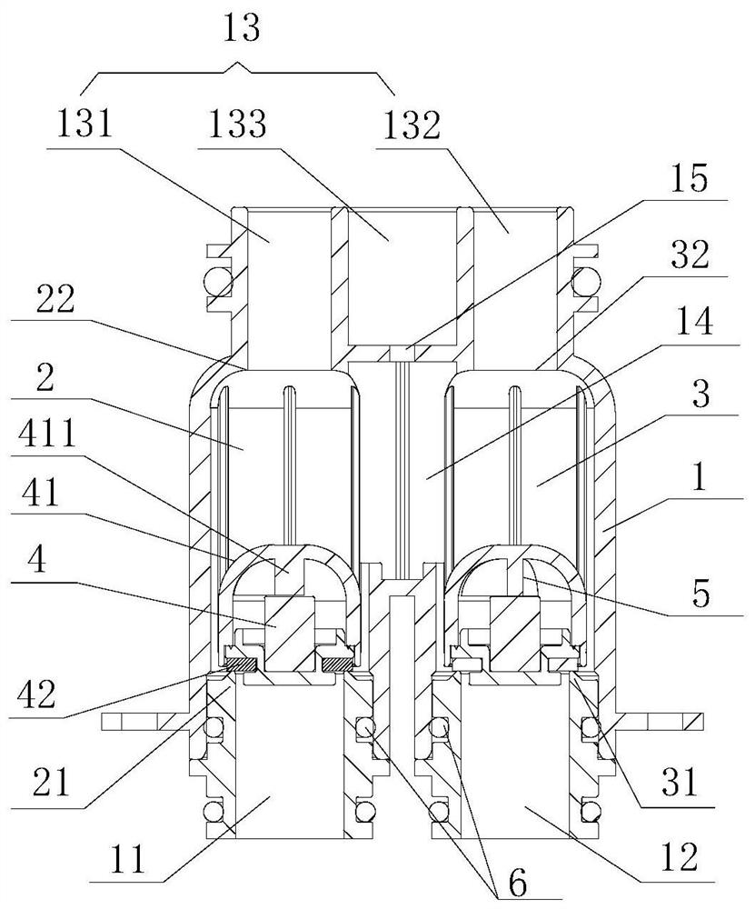
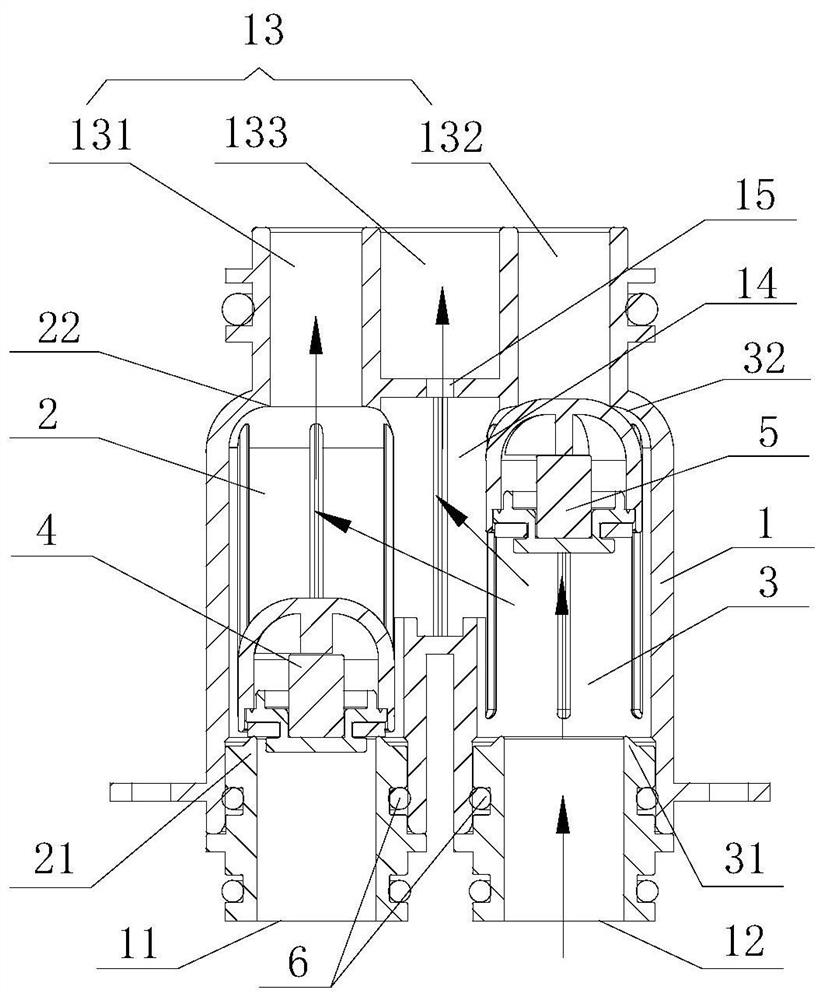
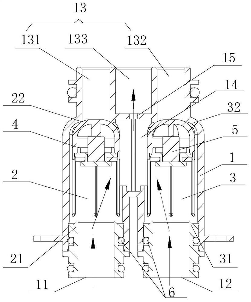
[0016] refer to Figure 1 to Figure 4 A waterway switching float valve of the present invention includes a valve body 1, a first float chamber 2, a second float chamber 3, a first float 4 and a second float 5, and the valve body 1 has a water inlet below the valve body 1 Passage A11, water inlet passage B12, with a water outlet passage 13 above, the valve body 1 has a first float chamber 2, a second float chamber 3, the first float 4 can be placed in the first float chamber 2 The second floating ball 5 can move in the second floating ball cavity 3, and there is a channel 14 connecting the two between the first floating ball cavity 2 and the second floating ball cavity 3, so The water outlet passage 13 includes a water outlet passage A131 communicating with the first float chamber 2, a water outlet passage B132 communicating with the second float chamber 3, and a water outlet passage C133 communicating with the channel 14, and the channel 14 is connected to the water outlet pas...


PUM


Abstract

The invention discloses a waterway switching floating ball valve which comprises a valve body, a first floating ball cavity, a second floating ball cavity, a first floating ball and a second floatingball. A water inlet channel A and a water inlet channel B are formed in the lower portion of the valve body, a water outlet channel is formed in the upper portion of the valve body, the valve body isinternally provided with the first floating ball cavity and the second floating ball cavity, the first floating ball can move in the first floating ball cavity, the second floating ball can move in the second floating ball cavity, and a channel for communicating the first floating ball cavity with the second floating ball cavity is formed between the first floating ball cavity and the second floating ball cavity. The water outlet channel comprises a water outlet channel body A communicating with the first floating ball cavity, a water outlet channel body B communicating with the second floating ball cavity and a water outlet channel body C communicating with the channel. A small hole for communicating the channel and the water outlet channel body C is formed between the channel and the water outlet channel body C. The floating ball valve adopts mechanical control, and two channels of inlet water are opened at the same time, so that mistaken feeding cannot be caused even if water inletand valve closing signals of a water valve are delayed.

Description

【Technical field】 [0001] The invention relates to the technical field of valves, in particular to a waterway switching float valve. 【Background technique】 [0002] With the improvement of washing machine automation, most washing machines are set to connect the detergent box for placing detergent or / and softener with the water inlet pipeline, and flush the detergent or / and softener in the detergent box into the washing tub through the water inlet middle. The invention patent with the application number 201811486646.X discloses a detergent delivery system. When the system switches functions, it needs to wait for the water inside to be drained (there are small holes in the system to drain water. After the water is drained, the floating ball will fall and the floating The density of the ball is less than that of water), and then the next step of function switching can be performed. The size of the small hole will affect the drainage speed. If the small hole is too small, it wi...

Claims


Application Information

Patent Timeline
Patent Type & Authority Applications(China)
IPC IPC(8): F16K11/056
CPCF16K11/056
Inventor 鲍鹏飞郭浩天
Owner HANGZHOU KAMBAYASHI ELECTRONICS
Features
  • R&D
  • Intellectual Property
  • Life Sciences
  • Materials
  • Tech Scout
  • Unparalleled Data Quality
  • Higher Quality Content
  • 60% Fewer Hallucinations
Learn More