Supercharge Your Innovation With Domain-Expert AI Agents!

hand tool machine

A technology of tools and machines, applied in the field of hand-held tools and machines, can solve problems such as difficult manipulation

Active Publication Date: 2022-04-19
FESTOOL GMBH
View PDF9 Cites 0 Cited by
  • Summary
  • Abstract
  • Description
  • Claims
  • Application Information

AI Technical Summary

Problems solved by technology

The manipulation is difficult

Method used


Image

  • hand tool machine
  • hand tool machine
  • hand tool machine

Examples


Embodiment Construction

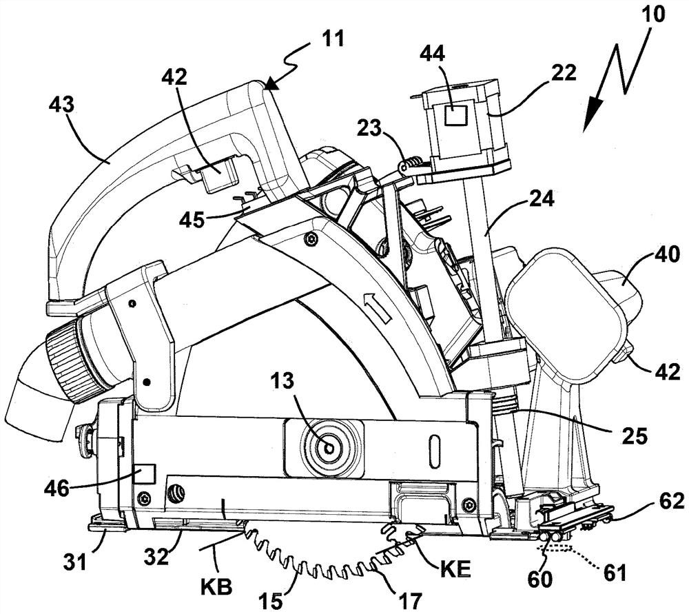
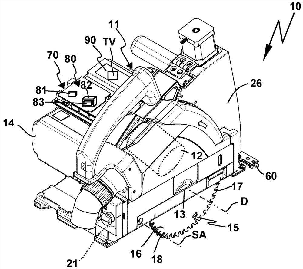
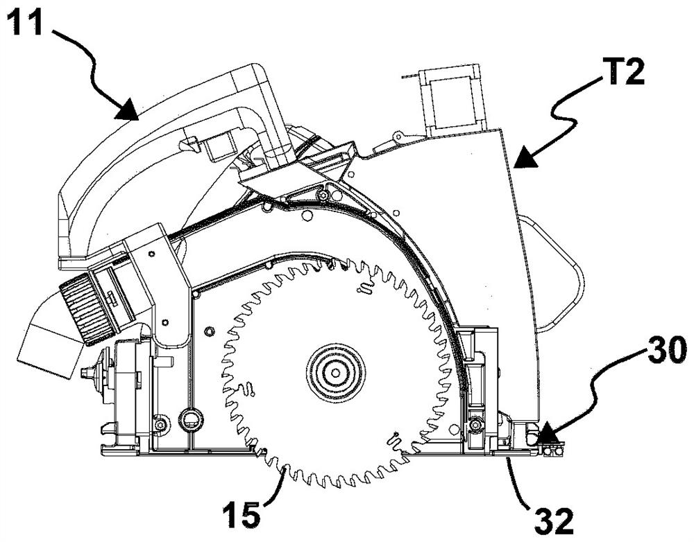
[0092] The machine tool 10 according to the figures has a guide element 30 with a guide plate 31 on which a guide surface 32 is arranged. A guide protrusion 52 of the guide receptacle 33 for guiding the guide rail 50 is provided at the guide surface 32 .

[0093] The machine tool 10 can be guided with its guide surface 32 directly along the workpiece surface WO of the workpiece W in order to introduce saw cuts thereon, for example. However, it is also possible to place the guide rail 50 with its bearing surface 53 on the workpiece surface WO in order to guide the machine tool 10 . The machine tool then slides with its guide surface 32 along a guide surface 51 which is arranged on the side of the guide rail 50 opposite the bearing surface 53 . Here, the guide projections 52 can engage into the guide receptacles 53 in order to guide the machine tool 10 in the normal working direction AR.

[0094] The machine tool 10 has a drive unit 11 with a drive motor 12 for driving the too...


PUM


Abstract

The invention relates to a movable machine tool (10) having a guide element (30) with a guide surface (32) for guiding all components relative to one another along a machining path (BA), in particular a machining line. A machine tool and a workpiece surface (WO) of the workpiece (W), wherein the machine tool has a drive unit (11) with a drive motor (12) for a drive arrangement arranged at the drive unit (11) A tool receptacle for receiving a working tool (15) and having a detection mechanism for detecting at least one workpiece reference (RB, RE), which is associated with the machining path (BA) and is provided for the A machining start position (BB) for the start of machining of the workpiece (W) by the working tool (15) or a machining end position for ending machining of the workpiece (W) by the working tool (15) (BE). It is provided that the tool receptacle is designed for driving the working tool ( 15 ) in rotation about an axis of rotation (D) and for adjusting the penetration depth of the working tool ( 15 ) into the workpiece by means of the tool The depth adjustment mechanism (20) of the machine can be adjusted between depth adjustment positions (T1, T2, T3), wherein the working tool has a cutting area at its radially outer periphery (17) for machining during construction In the case of an edge (KB, KE) cut into the workpiece (W), the machining edge depends on at least two depth adjustment positions (T1, T2, T3) having access to the at least one workpiece reference (RB, RE), the working tool does not protrude as far ahead of the guide surface in the at least two depth adjustment positions, and the machine tool has a depth preset mechanism (70) for determining A distance value (DB) of the distance from the machining edge (KB, KE) to the at least one workpiece reference (RB, RE) and used for determining a position for the depth adjustment (T1, T2, T3) depth preset value (TV).

Description

technical field [0001] The invention relates to a mobile machine tool for machining workpieces, ie a hand-held machine tool or a semi-stationary machine tool, wherein the machine tool has guide elements with guide surfaces for mutual alignment along a machining path, in particular a machining line. Guide the machine tool and the workpiece surface of the workpiece relative to each other, wherein the machine tool has a drive unit with a drive motor for driving a tool receptacle arranged on the drive unit for accommodating a working tool, wherein the machine tool has a detection mechanism For detecting at least one workpiece reference, which is assigned with respect to the machining path to a machining start position provided for the start of machining of the workpiece by the working tool or to a machining end position provided for the end of machining of the workpiece by the working tool . [0002] Furthermore, the invention relates to a method for operating a movable machine t...

Claims


Application Information

Patent Timeline
Patent Type & Authority Patents(China)
IPC IPC(8): B27B9/02B23D59/00
CPCB27B9/02B23D59/002B27G19/04
Inventor M·屈贝勒M·鲁施D·朔伊布勒
Owner FESTOOL GMBH
Features
  • R&D
  • Intellectual Property
  • Life Sciences
  • Materials
  • Tech Scout
  • Unparalleled Data Quality
  • Higher Quality Content
  • 60% Fewer Hallucinations
Learn More