
Element clamping device for element detection equipment

A detection equipment and clamping device technology, applied in workpiece clamping devices, manufacturing tools, etc., can solve problems such as poor versatility, inability to clamp components, and affect the effect of detection, and achieve stable fixation, stable movement, and not easy to shake. Effect

Inactive Publication Date: 2021-03-23
无锡索米科技有限公司
View PDF5 Cites 1 Cited by
  • Summary
  • Abstract
  • Description
  • Claims
  • Application Information

AI Technical Summary

Problems solved by technology

[0002] Components usually refer to electrical appliances, radios, instruments and other parts, such as electronic components, pneumatic components, etc., and commonly used electronic components include resistors, electric fuses, transformers, etc. When testing components, if there is no clamping for the components, Thus affecting the effect of subsequent detection, so a component clamping device for component testing equipment is needed
[0003] However, the existing component clamping device for component testing equipment can only fix components of uniform specifications when it is necessary to clamp components, but cannot clamp components of different sizes and specifications, so that Poor versatility, which makes it inconvenient for subsequent clamping operations

Method used


Image

  • Element clamping device for element detection equipment
  • Element clamping device for element detection equipment
  • Element clamping device for element detection equipment

Examples


Embodiment

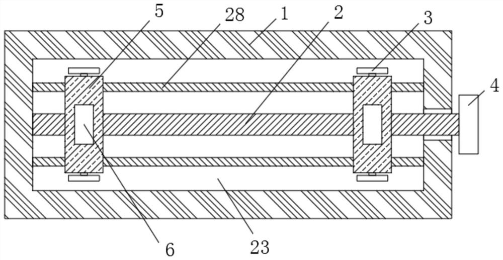
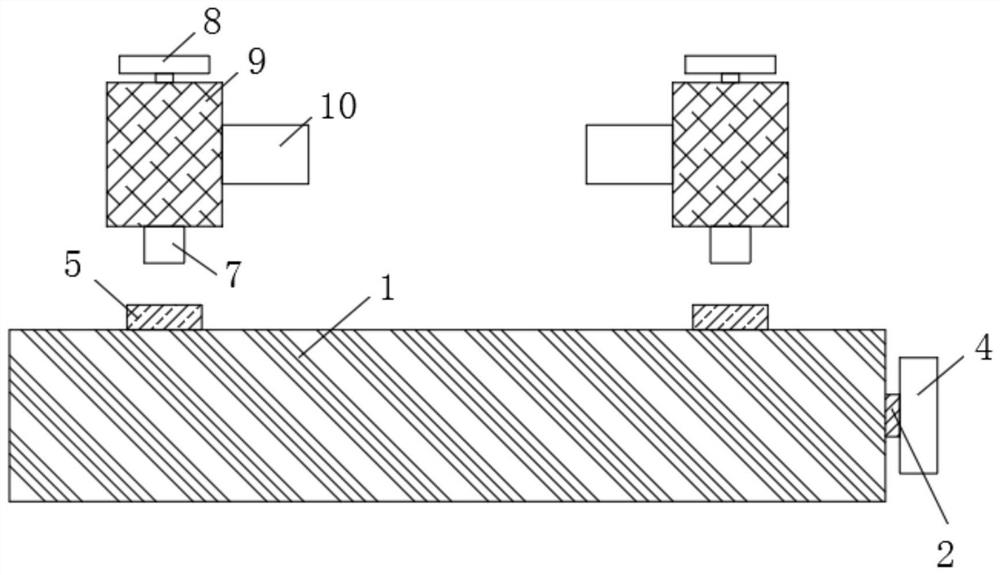
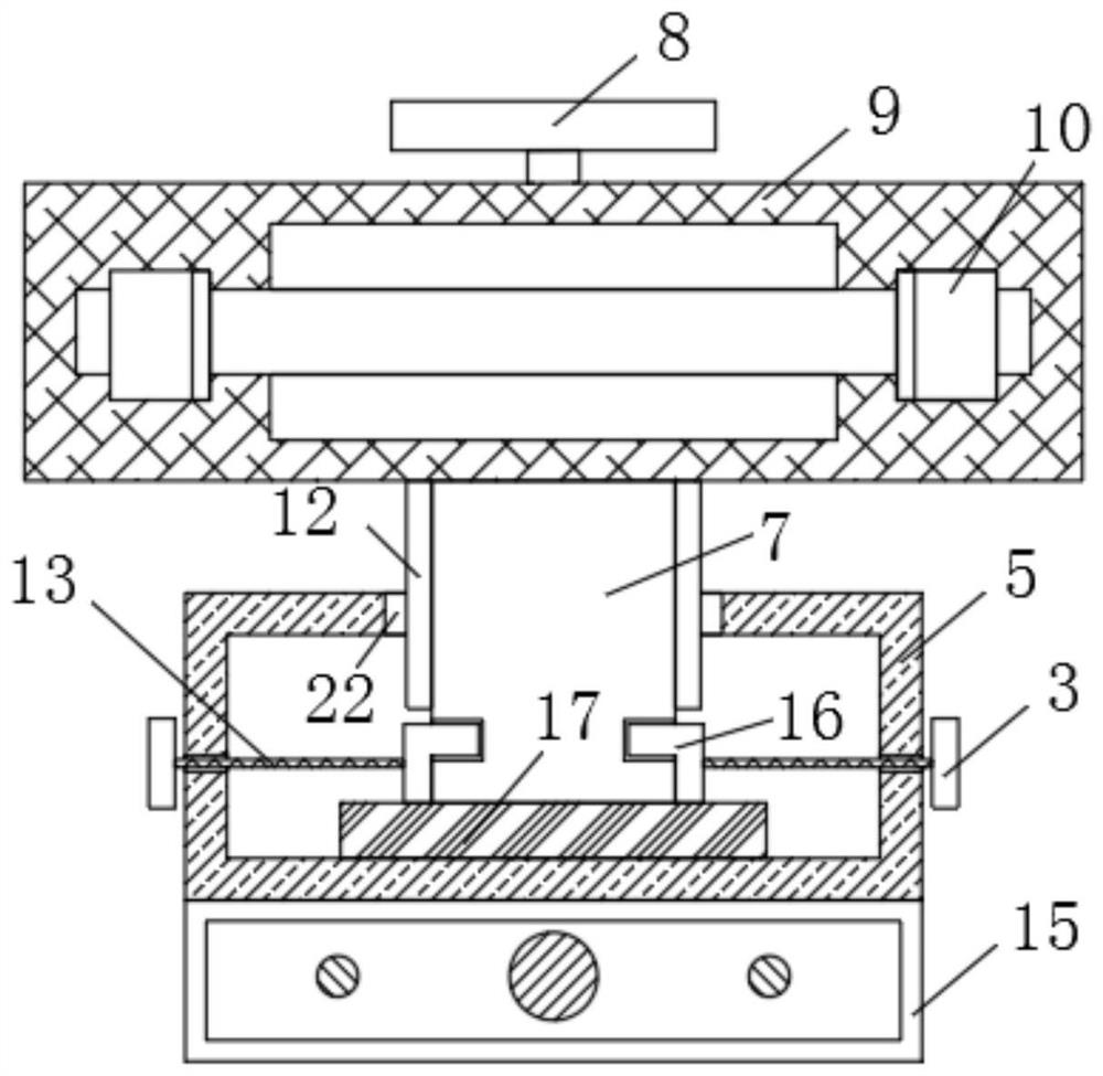
[0026] Example: such as Figure 1-6 As shown, a component clamping device for component testing equipment of the present invention includes a fixed table 1, a first rotating disk 4 is provided on one side of the fixed table 1, a moving mechanism 23 is provided inside the fixed table 1, and the fixed table 1 The top is symmetrically provided with two first movable blocks 5, and the top surfaces of the two first movable blocks 5 are all excavated with movable grooves 6, and the inside of the movable groove 6 is provided with a sliding mechanism 11. Inside are all provided with limit mechanism 24, both sides of two first movable blocks 5 are all provided with movable plate 3, all are fixedly connected with fixed warehouse 17 on the bottom end surface of two first movable blocks 5 inside, the inside of fixed warehouse 17 Be provided with limit mechanism 24, the top of two first movable block 5 is all provided with first limit box 9, the inside of first limit box 9 is provided with...


PUM


Abstract

The invention discloses an element clamping device for element detection equipment. The element clamping device comprises a fixing table, a first rotating disc is arranged on one side of the fixing table, a moving mechanism is arranged in the fixing table, two first movable blocks are symmetrically arranged at the top of the fixing table, movable grooves are dug in the top end surfaces of the twofirst movable blocks, sliding mechanisms are arranged in the movable grooves, limiting mechanisms are arranged in the two first movable blocks, and movable plates are arranged on the two sides of thetwo first movable blocks. The element clamping device has the beneficial effects that the effect of adjusting the distance between the two movable blocks can be achieved through the moving mechanism,so that two limiting boxes are driven to move so as to achieve the effect of fixing an element, with the cooperation of a clamping mechanism, the two sides of the element can be further limited, and by limiting the two sides, the front end and the rear end of the element, the element can be fixed more stably, and the phenomenon that the element is loosened is not likely to happen.

Description

technical field [0001] The invention relates to a clamping device, in particular to a component clamping device for component testing equipment, and belongs to the technical field of component clamping. Background technique [0002] Components usually refer to electrical appliances, radios, instruments and other parts, such as electronic components, pneumatic components, etc., and commonly used electronic components include resistors, electric fuses, transformers, etc. When testing components, if there is no clamping for the components, As a result, the effect of subsequent detection is affected, so a component clamping device for component testing equipment is needed. [0003] However, the existing component clamping device for component testing equipment can only fix components with uniform specifications when the components need to be clamped, and cannot clamp components with different sizes and specifications. The versatility is poor, and it is inconvenient to carry out...

Claims


Application Information

Patent Timeline
Patent Type & Authority Applications(China)
IPC IPC(8): B25B11/00
CPCB25B11/00
Inventor 刘海涛
Owner 无锡索米科技有限公司
Learn More