
Amphibious bridge suitable for automobile loading, unloading and transportation

An amphibious, automobile technology, applied in the field of transportation, can solve the problems that ferries do not have, dry ditch bridges on land do not have the function of ferrying materials and equipment for water navigation, and achieve the effect of overcoming river obstacles

Pending Publication Date: 2021-03-23
CHINA HARZONE IND CORP
View PDF0 Cites 1 Cited by
  • Summary
  • Abstract
  • Description
  • Claims
  • Application Information

AI Technical Summary

Problems solved by technology

[0002] The dry ditch bridges erected by special vehicles are loaded, erected and withdrawn by special bridge vehicles, and are limited to use on land. They mainly overcome passing obstacles such as ditches, pits, road subsidence, slopes, and shore beaches, and realize road restoration. Traffic, opening up new channels to meet the needs of materials and equipment to pass through land obstacles smoothly, but the dry ditch bridge on land does not have the function of ferrying materials and equipment by water navigation
[0003] The ferries used to transport materials and equipment on water use sealed floating bodies on the water, and power propellers and driving control systems are installed in the floating bodies to carry out water crossings. They are limited to water use and are mainly aimed at waters such as rivers, rivers, lakes, and seas. Realize crossing obstacles in water navigation and meet the needs of materials and equipment to pass through water obstacles smoothly; however, ferries do not have the function of erecting dry ditch bridges on land to pass through ditches and pits

Method used


Image

  • Amphibious bridge suitable for automobile loading, unloading and transportation
  • Amphibious bridge suitable for automobile loading, unloading and transportation
  • Amphibious bridge suitable for automobile loading, unloading and transportation

Examples


Embodiment Construction

[0051] The present invention will be described in detail below with reference to the accompanying drawings and examples.

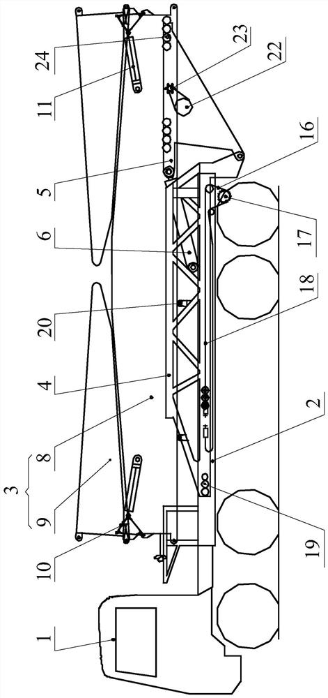
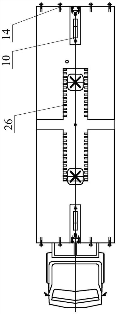
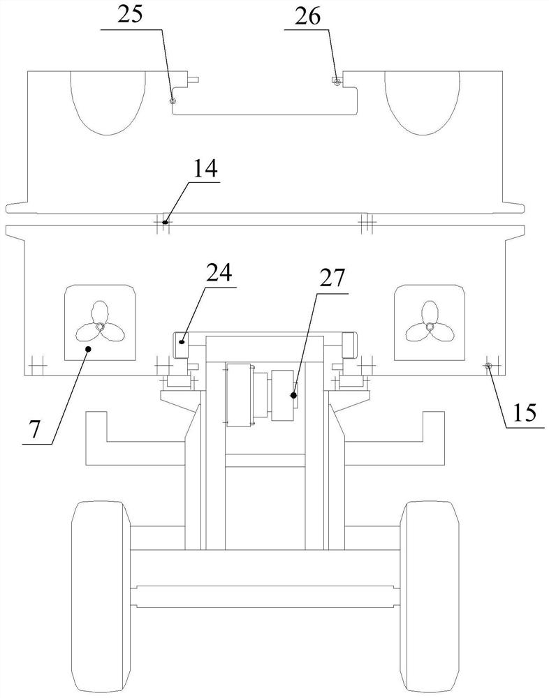
[0052] in, figure 1 , figure 2 and image 3 A schematic diagram of the overall structure of the amphibious bridge is shown, Figure 4 , Figure 5 as well as Figure 6 A schematic diagram of the structure of the bridge body 3 is shown, Figure 7 It shows the schematic diagram of the structure of the amphibious bridge erected on the land on the trench, Figure 8 It shows the schematic diagram of the structure of the amphibious bridge when one end is erected on the water, Figure 9 A schematic diagram of the structure of the amphibious bridge navigating on water is shown.

[0053] The invention provides an amphibious bridge suitable for vehicle loading and unloading transportation, such as figure 1 As shown in the structure, the amphibious bridge includes a bridge vehicle 1, a vehicle frame 2, a bridge body 3, a mobile frame 4, an erection frame 5, a...


PUM


Abstract

The invention discloses an amphibious bridge suitable for automobile loading, unloading and transportation. The amphibious bridge comprises a bridge vehicle, a vehicle frame, a bridge body, a movableframe, an erecting frame, an erecting oil cylinder and a water propeller. The vehicle frame is fixedly mounted on the bridge vehicle and used for being transported through the bridge vehicle. The movable frame can be mounted on the vehicle frame in a reciprocating sliding mode in the length direction of the bridge vehicle. The bottom of the erecting frame is hinged to the tail of the movable frame, and the erecting oil cylinder is hinged between the top of the erecting frame and the movable frame and used for driving the erecting frame to swing in the vertical plane. The bridge body is provided with the water propeller, can be supported on the top of the movable frame and the top of the erecting frame in a reciprocating mode in the length direction of the bridge vehicle, and has a folded state and an erected state. According to the amphibious bridge, a land dry ditch bridge and an overwater ferry are combined into a whole, so that not only can dry ditch obstacles be overcome on land, but also river obstacles can be overcome on the water surface, and the dual requirements that materials and equipment smoothly pass through the amphibious obstacles are met.

Description

technical field [0001] The invention relates to the technical field of transportation, in particular to an amphibious bridge suitable for vehicle loading and unloading transportation. Background technique [0002] The dry ditch bridges erected by special vehicles are loaded, erected and withdrawn by special bridge vehicles, and are limited to use on land. They mainly overcome passing obstacles such as ditches, pits, road subsidence, slopes, and shore beaches, and realize road restoration. Traffic, open up new channels, to meet the needs of materials and equipment to pass through land obstacles smoothly, but the dry ditch bridge on land does not have the function of ferrying materials and equipment by water navigation. [0003] The ferries used to transport materials and equipment on water use sealed floating bodies on the water, and power propellers and driving control systems are installed in the floating bodies to carry out water crossings. They are limited to water use an...

Claims


Application Information

Patent Timeline
IPC IPC(8): E01D15/00E01D15/14E01D15/22B63B35/00
CPCE01D15/00E01D15/14E01D15/22B63B35/00
Inventor 朱卫忠谢北萍赵军科陈凯熊志汤云溪胡杰
Owner CHINA HARZONE IND CORP
Learn More