Impact test device for rod-shaped anchoring assembly
An impact test and anchoring technology, applied in the direction of using a single impact force to test the strength of materials, measuring devices, instruments, etc., can solve the problems of high safety risk and inconvenient operation, and achieve a low safety risk factor, convenient operation and cost reduction. Effect
- Summary
- Abstract
- Description
- Claims
- Application Information
AI Technical Summary
Problems solved by technology
Method used
Image
Examples
Embodiment 1
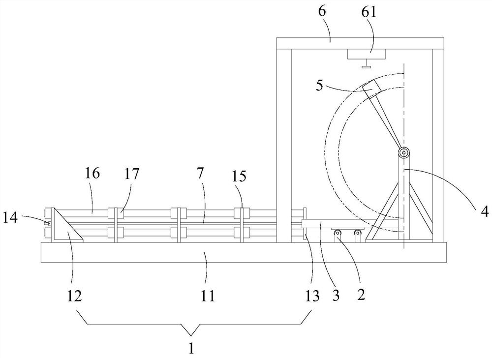
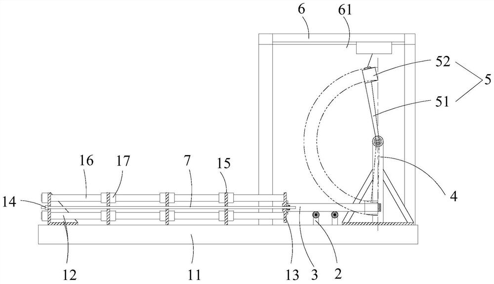
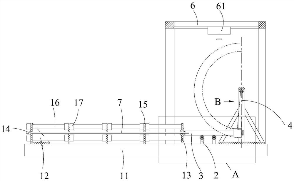
[0052] Such as Figure 1-7 As shown, a kind of impact test device for the rod-shaped anchor assembly described in this embodiment,
[0053] Including base 1, support frame 4 and slidable plate 13, wherein,
[0054] The base 1 is used to place the rod-shaped anchor assembly 7 horizontally, and the base 1 is used to connect with the end of the rod-shaped anchor assembly 7 away from the support frame 4;
[0055] A pendulum 5 is hinged on the support frame 4;
[0056] A supporting sliding device 2 is arranged between the base 1 and the supporting frame 4, and the top of the supporting sliding device 2 is supported and connected with a force transmission frame 3, and the force transmission frame 3 is arranged horizontally, and the force transmission frame 3 is arranged along the The horizontal direction cooperates with the movement of the supporting sliding device 2, the end of the force transmission frame 3 close to the base 1 has a first end plate 31, and the end of the force t...
Embodiment 2
[0077] Such as Figure 1-9 As shown, the impact test device for the rod-shaped anchor assembly described in this embodiment is different from Embodiment 1 in that there are at least two seat plates 15, and the seat plates 15 are adjacent to each other. Arranged at intervals, all of the seat plates 15 are provided with fourth through holes 151 for the rod-shaped anchor assembly 7 to pass through, and all of the fourth through holes 151 are coaxially arranged with the first through holes 131 .
[0078] The seat board 15 is connected with the support 12 through a connecting rod 16, and the connecting rod 16 runs through all the seat boards 15, and the two sides of the slidable plate 13 are provided with screws that are threadedly connected with the connecting rod 16. A sleeve 17, one end of the connecting rod 16 is connected with the support 12.
[0079] In the test, the most ideal state is that the first through hole 131, the second through hole 311, the third through hole 121 ...
PUM
 Abstract
Description
Claims
Application Information
 - R&D
- Intellectual Property
- Life Sciences
- Materials
- Tech Scout
- Unparalleled Data Quality
- Higher Quality Content
- 60% Fewer Hallucinations
Browse by: Latest US Patents, China's latest patents, Technical Efficacy Thesaurus, Application Domain, Technology Topic, Popular Technical Reports.
© 2025 PatSnap. All rights reserved.Legal|Privacy policy|Modern Slavery Act Transparency Statement|Sitemap|About US| Contact US: help@patsnap.com


