Guide wheel type inclinometer storage device with adjusting function

A storage device, inclinometer technology, applied in the directions of transportation and packaging, multi-axis trolleys, trolley accessories, etc., can solve the problem that the inclinometer model cannot adjust the clamping position and so on

Inactive Publication Date: 2021-03-26
童庆
View PDF0 Cites 0 Cited by
  • Summary
  • Abstract
  • Description
  • Claims
  • Application Information

AI Technical Summary

Problems solved by technology

[0004] 1. The existing storage device for guide wheel inclinometers cannot adjust the clamping position according to different inclinometer models;
[0005] 2. The existing storage device for guide wheel inclinometers cannot choose to move the device by traction or hand-held movement according to the needs. Therefore, we propose a storage device for guide wheel inclinometers with adjustment function to solve the current problem. some problems

Method used


Image

  • Guide wheel type inclinometer storage device with adjusting function
  • Guide wheel type inclinometer storage device with adjusting function
  • Guide wheel type inclinometer storage device with adjusting function

Examples


Embodiment 1

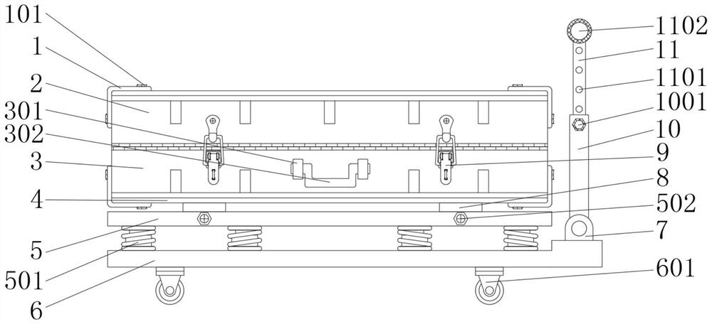
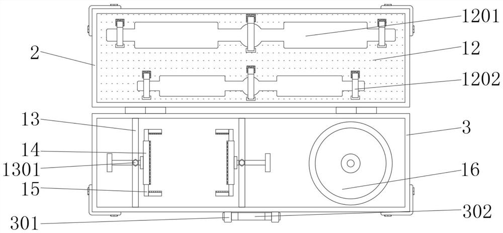
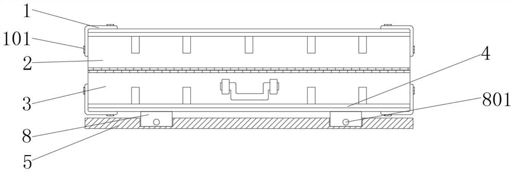
[0026] An embodiment provided by the present invention: a storage device for a guide wheel type inclinometer with adjustment function, including an upper storage box 2, a lower storage box 3 and a base 6, the bottom of the base 6 is fixedly equipped with a wheel 601, the base The top of 6 is equipped with sleeve rod 10 through movable part 7, and the inside of sleeve rod 10 is equipped with inner rod 11, and the top of base 6 on one side of movable part 7 is fixedly equipped with shock absorbing plate 5, and shock absorbing plate 5 and The first spring 501 is fixedly installed between the bases 6, the surface at both ends of the shock absorbing plate 5 is movable with a fixed bolt 502, and the top of the shock absorbing plate 5 is fixedly installed with a lower storage box 3, between the lower storage box 3 and the shock absorption plate 5. A connecting block 8 is fixedly installed between them, the surface of the connecting block 8 is provided with a bolt hole 801, and the bol...

Embodiment 2

[0028] On the basis of Example 1, please refer to Figure 1-5, Another embodiment further provided by the present invention: a storage device for a guide wheel type inclinometer with adjustment function, comprising an upper storage box 2, a lower storage box 3 and a base 6, the bottom of the base 6 is fixedly equipped with wheels 601, the top of the base 6 is movably installed with a sleeve rod 10 through the movable part 7, and the inner rod 11 is movably installed inside the sleeve rod 10, and the top of the base 6 on the side of the movable part 7 is fixedly installed with a shock absorbing plate 5, and the shock absorber The first spring 501 is fixedly installed between the plate 5 and the base 6, the surface of the shock absorbing plate 5 two ends is movably equipped with a fixed bolt 502, and the top of the shock absorbing plate 5 is fixedly installed with a lower placement box 3, and the lower placement box 3 is connected with the shock absorber. A connection block 8 is...


PUM


Abstract

The guide wheel type inclinometer storage device with the adjusting function comprises an upper containing box, a lower containing box and a base, a damping plate is fixedly installed at the position,on one side of a movable piece, of the top of the base, a first spring is fixedly installed between the damping plate and the base, and the lower containing box is fixedly installed at the top of thedamping plate; a connecting block is fixedly installed between the lower containing box and the damping plate, a fixing plate is fixedly installed in the lower containing box, a clamping plate is movably installed between the fixing plates, a movable frame is movably installed in the clamping plate, and a retractor is fixedly installed in the position, on the other side of the fixing plate, of the interior of the lower containing box. And a placing block is fixedly mounted in the upper placing box. By arranging a series of structures, the clamping position of the device can be adjusted according to different inclinometer models in the using process, and a user can conveniently select to pull the device to move or move the device in a hand-held mode according to needs.

Description

technical field [0001] The invention relates to the technical field of construction inclinometers, in particular to a storage device for a guide wheel type inclinometer with an adjustment function. Background technique [0002] Since the 1980s, my country has introduced inclinometers produced by the United States, Japan, and the United Kingdom to monitor some major geotechnical projects in situ, and achieved good results. Some related research institutions have subsequently developed resistance strain gauges, accelerometers, etc. Intelligent inclinometers such as type and electronic gauges need to use a placement device when storing the inclinometer, but the existing placement device cannot adjust the clamping position according to different models of the inclinometer, so a device with Storage device for guide wheel inclinometers with adjustment function. [0003] The defective that existing guide wheel type inclinometer storage device exists is: [0004] 1. The existing sto...

Claims


Application Information

Patent Timeline
Patent Type & Authority Applications(China)
IPC IPC(8): B62B3/04B62B5/00
CPCB62B3/04B62B5/00B62B5/0006
Inventor 童庆
Owner 童庆
Why Eureka
Try Eureka