Capping head, system and method

A capping and capping head technology, applied in the field of capping heads, can solve problems such as damage, affecting the cost of the capping process, and energy consumption of the capping system

Pending Publication Date: 2021-03-26
佩里科尼股份公司
View PDF6 Cites 0 Cited by
  • Summary
  • Abstract
  • Description
  • Claims
  • Application Information

AI Technical Summary

Problems solved by technology

[0019] The presence of such high forces leads to an energy consumption of the capping system which can significantly affect the cost of the capping process and cause greater damage in case of failure

Method used


Image

  • Capping head, system and method
  • Capping head, system and method
  • Capping head, system and method

Examples


Embodiment Construction

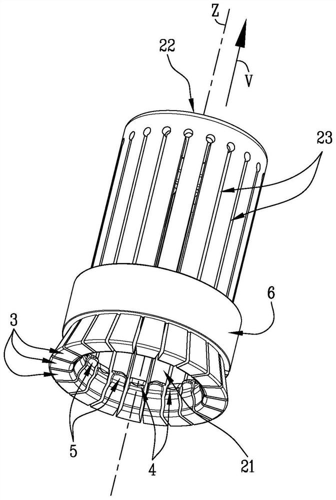
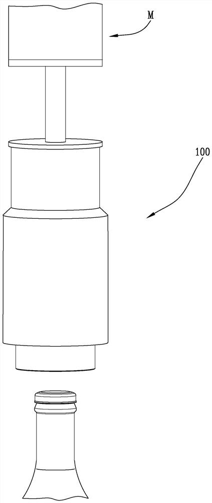
[0034] Referring to the drawings, numeral 1 designates a capping head designed to cap containers B by means of caps T by pressing.

[0035] Preferably, container B is a bottle.

[0036] More preferably, container B is a glass bottle.

[0037] The cap T is made of metallic material such as steel or aluminum.

[0038] Preferably, the cover T includes a metal cap and a plastic seal.

[0039] More preferably, the metal cap of closure T has a crimp, ie in the end portion of its side wall.

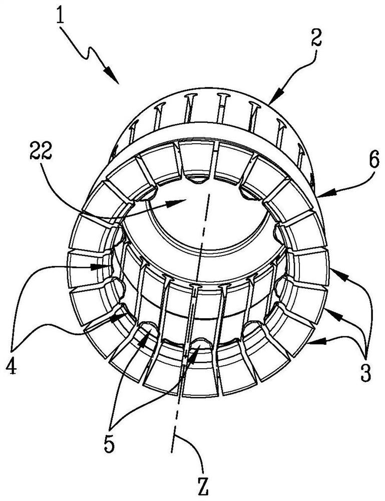
[0040] According to another aspect of the invention, the capping head 1 comprises a hollow body 2 extending around the longitudinal axis Z of the capping head 1 .

[0041] Preferably, when the capping head is in operation, said longitudinal axis Z coincides with the vertical axis, ie with the axis perpendicular to the horizontal plane on which the container B rests.

[0042] Thus, the body 2 has a lower opening 21 and an upper opening 22 positioned above the lower opening 21 with respect to ...


PUM


Abstract

Described is a capping head (1) for closing a container (B) using a metallic cap (T), comprising a main body (2), a plurality of capping ends (3) having on their inner face a capping profile (4, 5) and a capping ring (6) configured for elastically deforming the plurality of capping ends (3) by means of a relative translation along the longitudinal axis (Z).

Description

technical field [0001] The present invention relates to a capping head for application to containers, such as glass bottles, by deforming a closure by pressure. [0002] The context of the invention is closures which, once applied to containers, are removed using a tool such as a corkscrew capable of transferring the force exerted by the user using a system of levers to the closure. [0003] The invention also relates to a capping system comprising a capping head and a capping method for applying a cap to said container. [0004] The capping head according to the invention can be used to close containers designed to hold pressurized liquid products. Background technique [0005] Pressurized liquid products present in containers closed with the closure system and method according to the present invention include any liquid, for example, carbonated non-alcoholic beverages or beer. [0006] The closure according to the invention is particularly, but not exclusively, suitable ...

Claims


Application Information

Patent Timeline
IPC IPC(8): B67B3/12
CPCB67B3/10B67B3/14B67B3/12
Inventor F·库塔约F·莫塞利D·纳尔迪
Owner 佩里科尼股份公司
Why Eureka
Try Eureka